.ac plant .air conditioning
Brief explanation:
Temp – com outlet- 70-90, condenser outlet- 38-45, TXV out- 0-10, evaporator out-7-15,
Superheat- evaporator outlet 5-6 and compressor inlet around 10 degree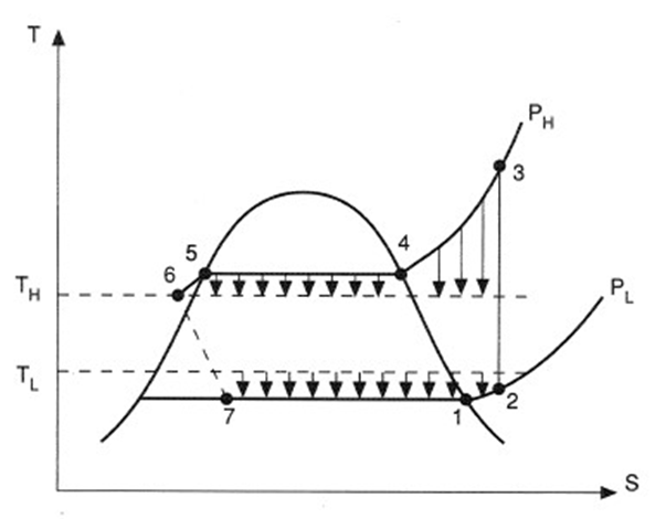
Figure 4. T-S diagram for basic vapor compression cycle.
The cycle processes can be described as follows:
7-1 Evaporation of the liquefied refrigerant at constant temperature T1 = T7.
1-2 Superheating of the vapor from temperature T1 to T2 at constant pressure PL.
2-3 Compression (not necessarily adiabatic) from temperature T2 and pressure PL to temperature T3 and pressure PH.
3-4 Cooling of the super-heated vapor to the saturation temperature T4.
4-5 Condensation of the vapor at temperature T4 = T5 and pressure PH.
5-6 Subcooling of the liquid from T5 to T6 at pressure PH.
6-7 Expansion from pressure PH to pressure PL at constant enthalpy.
A further difference between the real cycle and the ideal is that temperature T1 at which evaporation takes place is lower than the temperature TL of the cold region so heat transfer can take place. Similarly the temperature T4 of the heat rejection must be higher than the hot region temperature TH to bring about heat transfer in the condenser.
It is usual for the vapor-compression cycle to be plotted on a pressure-enthalpy (p-h) diagram as shown in
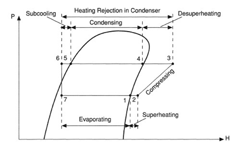
Figure 5. p-h representation of vapor compression cycles.
types of fault
- Loss of oil from crankcase
- Excessive amount of oil in the crankcase
- Refrigerant leakages
- Refrigerant undercharged
- Refrigerant overcharged
- Fall off in refrigerating effect
- Short cycling on HP cut out
- Short cycling on LP cut out
- Moisture in the system
- Air in the system
- Frost on evaporator coils
- Compressor drawing in refrigerant liquid
- Noisy compressor
- Poor cooling in condenser
“Loss of oil” from the crankcase:
1.1) Low crankcase oil level – operational leakages.
1.2) Foaming – sudden “disappearance” of oil.
Operational Leakages due to malfunction of the mechanical seals resulting :
a) Loss of oil.
b) Loss of refrigerant – the end clearance of the piston/scraper rings allows a small amount of refrigerant gas to reach the crankcase
1.2) Foaming can happen when –
a) Pressure drops rapidly in the evaporator.
b) Compressor high capacity to pull down pressure rapidly.
c) Crankcase space developing a low pressure condition.
With the formation of Low Pressure within the crankcase space :
– lubricating oil is unable to hold the small bubbles in the oil.
– small bubbles enlarge , attain buoyancy
– bubbles raise to the oil surface
Excessive amount of oil in the crankcase
Do not top up the oil level in the crankcase to excessive high level. It may cause :
- Overloading of the OIL SEPARATOR
- Oil passing to the condenser and the rest of system – hampering optimum heat transfer.
- Always maintain the oil level at the recommended level as indicated on the sight glass.
Indication of refrigerant leakages:
- Low refrigerant level in sight glass
- Large bubbles in sight glass
- Oil weeping at joint and connection
- Relative lower pressure readings across the system (LP,OP & HP)
- High superheat at compressor suction
- Compressor running continuously – room temperature not reducing
Fall off in refrigerating effect (over a short period)
- Refrigerant loss through valve stem gland packing, pipes, fittings compressor etc
- Broken suction, discharge valves of compressor
- Belt slipping – motor to compressor
- Icing of expansion valve
HP cut out
- Insufficient or intermittent water flow for condenser cooling
- Relatively higher temperature of cooling water
- Scaled or fouled condenser
- Overcharging of refrigerant
- Air in the system
Short cycling on LP cut out
- Malfunction LP pressure switch
- Evaporator coils heavily frosted
- Strainer for TEV chocked
- Leaky discharge valves
- Deflective expansion valve
- Refrigerant undercharge
Refrigerant undercharged
- Large bubbles noted in sight glass
- Lower LP , OP , HP pressure
- Continuous running of compressor- room temperature not reducing
- Relative less frosting on compressor suction line/valve
- System performance drops
Refrigerant overcharged
- Sight glass refrigerant level higher than normal
- Higher LP/OP/HP pressure
- Compressor stopping on HP cutout
- Severe frosting on compressor suction line/valve – Malfunction of TEV
Moisture in the system
- Frosting on inlet side of expansion valve
- Low LP pressure
- Corrective Actions : Renew the filter/drier.
Water (not removed by the filter/Drier) if present with the refrigerant at the
- TEV will become ice – restricting proper refrigerant flow.
In a good working order refrigeration system, a thin layer of ice of about 2-4mm will be formed on the TEV (external body). The ice formation is due to the unavoidable “flash off” of liquid refrigeration when it passes through the orifice. The presence of an extra volume of ice formation on the TEV indicates that Excessive flash off is taking place.
Frost on evaporator coils
- Compressor runs longer
- Short cycling on LP switch
- Performance drops
- Low suction pressure – Refrigerant temperature drops to 0 degree celsius or lower
Frost coming back in evaporator coil continuously because of relative lower pressure existing in the coils. The low pressure could be due to refrigerant leakages, dirty filter/drier, dirty strainer of the TEV – any reasons that results in a lower than normal pressure within the coils. The pressure of the refrigerant directly affects the temperature of the refrigerant in the coil. The lower the pressure – the lower will be the temperature of the refrigerant. If the temperature of the refrigerant is near to or lower than or at the freezing point of water, high relative humidity air flowing pass the evaporator coil will cause ice to be built up persistently.
Remedy : Restore the working pressure of the LP side to the marker’s recommended value – bring the operating temperature of the refrigerant away from the freezing point of water.
Compressor drawing in refrigerant liquid
Usually is due to malfunction of TEV resulting :
- Excessive frosting at inlet valve body of the compressor and/or icing on the cylinder head.
- Oil level at compressor sump reduced
- High suction pressure
- Noisy compressor operation
Noisy compressor
- Liquid knock / hammering*
- Lack of lubrication
- Internal components damaged
Air in the system
- High condenser pressure (HP pressure)
- Jumping of pressure gauges pointer
- Compressor noisy
- Small bubbles at sight glass
- Relative small difference in cooling water in & out temperature – Less heat transfer
Air (or moisture) can be accidentally introduced into the refrigeration system during topping up of refrigerant into system or during topping up of lubrication oil for the compressor.
Air will finally be accumulated in the condenser.
1) Mainly nitrogen(78%) and oxygen(21%) – it is not possible to condense air with the cooling water.
2) The volume of air will occupy the space at the top of the condenser –
a) prevents refrigerant gas entering the condenser.
b) reduces the total cooling surface area for the refrigerant.
3) Result in
(a) higher pressure reading in the HP side of the system and
(b) reduction in temperature differential of the cooling water.Cooling water inlet temperature minus outlet temperature.
Removal of Air :
1) Connect a refrigerant recovery bottle to the purging cock (of the condenser) via a flexible hose.
2) Remove the air until the flexible hose is cold or/and the cooling water difference temperature of about
8-10 degree Celsius is achieved.
Note : The refrigerant used although do not contribute to ozone depletion , it is still a greenhouse gas Therefore , it should not be released directly into the atmosphere
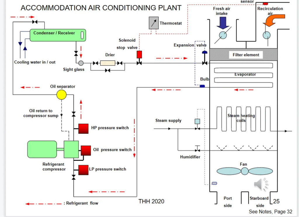
Master solenoid valve
The master solenoid is installed after the receiver, which is controlled by the control unit. In case of sudden stoppage of the compressor, the master solenoid also closes, avoiding the flooding of the evaporator with refrigerant liquid