
.crankcase explosion .crank case explosion .cce
Causes leading to crankcase explosion
The causes of crank case explosion is the hot spot.
Sources of hot spot:
1. bearings:
·Main bearings.
· Bottom end bearings.
· Crosshead- bearings, guide shoes/slides.
· Gudgeon pin bearings. (4 stroke)
· Transmission gear/ chain gear.
2. Piston crown crack
3. Hot piston.
4. Hot gases blow past.
5. Scavenge fire.
Source of fuel:
· Lubricating oil vapor.
· Lubricating oil contaminated by fuel vapor.
· Leaky fuel injector causing semi-burnt fuel to enter crankcase.
· Piston crown crack
a. primary explosion:
- The cause of crank case explosion is the hot spot.
- under normal running condition air in the crankcase will contain oil droplets by system oil splashing.
- If hot spots exist, some oil will encounter it and will be vaporized,
- This vaporized oil circulates to cooler region of crankcase and condense to form white mist.
- this white mist is combustible at certain concentration.
- If this mist is circulated back to the hot spot with this concentration, it will be ignited, and primary explosion will take place.
Secondary Explosion:
- After primary explosion sufficient pressure and shock wave will build to rupture the crankcase door unless it is released by c/c relief valve.
- In this event low pressure wave will draw air back into the crankcase where it will mix with vaporized and burning oil to create secondary explosion.
How to prevent:
- Avoid hot spot by proper engine maintenance & operation.
- Avoid fuel contamination and overheating of lube oil
- Detect vapor generation at early stage by oil mist detectors.
- Maintain Crankcase relief door properly to prevent secondary explosion.
Warning and prevention devices:
· Oil mist detector: Range 0-10% LEL, Alarm 5% LEL (2.5 mg/L).
· Crankcase pressure relief door: opening pressure 0.2 bar maximum.
Action/ standing order in the event of OMD alarm:
- Upon OMD alarm additional generator should started & take on load
- Do not check or reset the OMD locally
- Engine will auto-slow down
- Inform bridge to stop engine
- All personnel leave engine room immediately
- Enter engine room only after engine has come to a complete stop or after30 minutes whichever is longer.
- Do not stop the LO pump
- Open the indicator cock
- Approach to turning gear should be away from the crankcase doors with relief valves
- Turn the engines for 30 minutes
Engine should be sufficiently cooled before crankcase doors are opened for inspection
Oil mist detector
Fitting of Oil Mist Detector gives early warning & slowdown, hence reduce the intensity.
consist of –
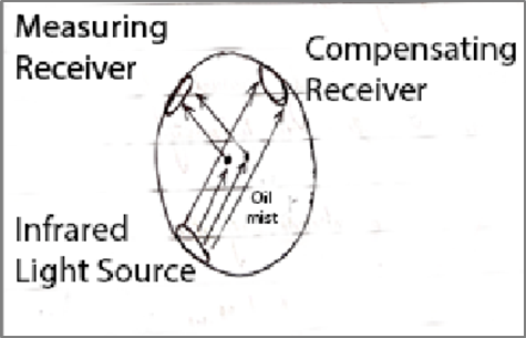
1. Infra- red light source transmitter
2. Compensating receiver
3. Measuring receiver
Operation:
- when infra-red light source start transmitting, some lights are directly received by compensating receiver and rest lights are being scatter by oil particles received by measuring receiver
- Compensating receiver situated directly opposite to the transmitter, which measures the amount of contamination building upon the transmitter.
- Measuring receiver is install 90 degrees to the transmitter. The amount of scattered light received by measuring receiver almost linearly indicates mist concentration in the crankcase.
If your oil mist detector breaks down, how would you safely continue operating your main engine?
- Engine room must be manned (no UMS)
- Using laser to measure crankcase door temperature
- Check temperature of breather pipe
- Fumes being emitted through the breather pipe at funnel oil mist box
- High lub oil bearing temperatures
- Higher piston cooling oil temperatures
- High thrust bearing temperature
- Chain case compartment temperature
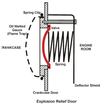
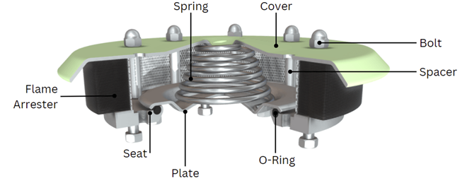
Crankcase relief valve
.crankcase relief valve .cc valve .c/c valve
Purpose and Function
Crankcase relief valves serve two critical functions:
- Relieve excess pressure inside the crankcase to normalize internal pressure
- Prevent flames from escaping the crankcase in case of an explosion
These valves are essential safety devices designed to mitigate the risks associated with crankcase explosions, which can have severe consequences including injury to personnel and extensive engine damage.
Design and Operation
Crankcase relief valves are:
- Lightweight, spring-loaded, self-closing devices
- Designed to open quickly at a pressure not exceeding 0.02 N/mm2 (0.2 bar)
- Constructed with valve discs made of ductile material to withstand shock.
The valves operate by:
- Opening rapidly when internal crankcase pressure increases between 0.2-1.0 bar
- Closing positively and rapidly after pressure is relieved
- Preventing the ingress of fresh air (non-return functionality