
.avr
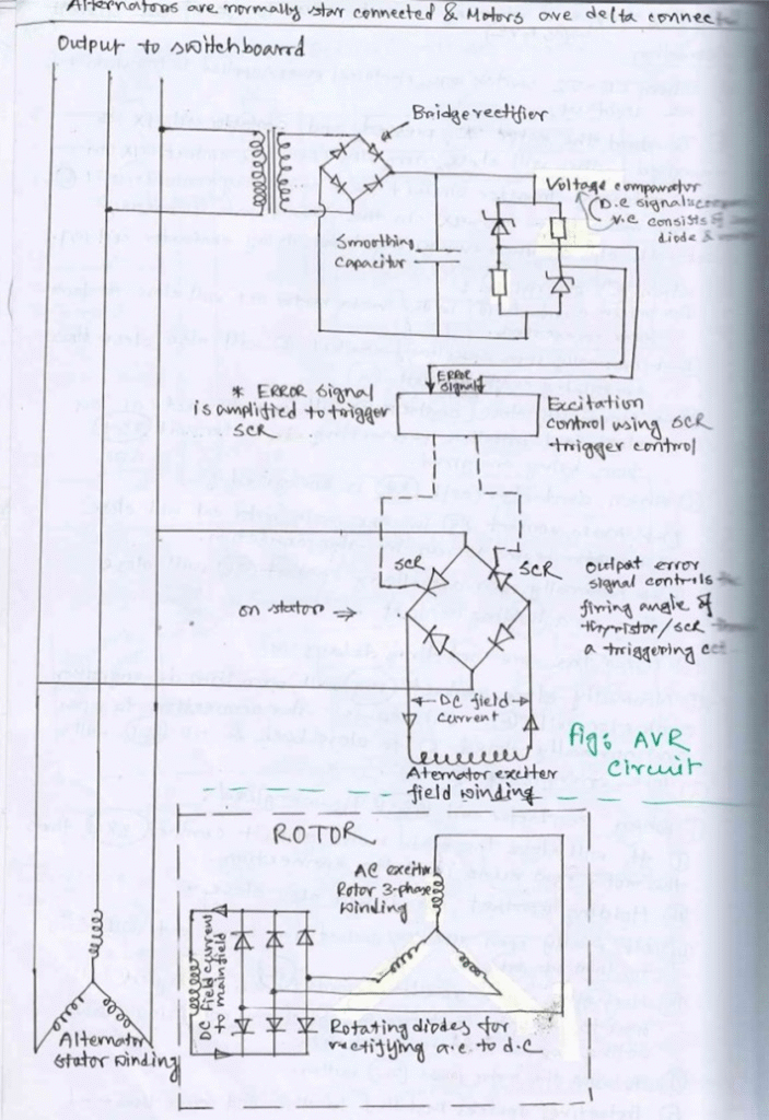
The key components in this AVR circuit are:
- Alternator (generator)
- Automatic Voltage Regulator (AVR) unit
- Exciter
- Main transformer
Voltage Generation
- The alternator, which is typically star-connected, generates AC voltage through electromagnetic induction as it rotates.
- The generated voltage is fed to the main transformer, which steps up or steps down the voltage to the desired level for distribution.
Voltage Regulation
- The AVR unit continuously monitors the output voltage of the alternator.
- If the output voltage deviates from the desired setpoint, the AVR adjusts the excitation current supplied to the exciter.
- If the output voltage is too low, the AVR increases the excitation current.
- If the output voltage is too high, the AVR decreases the excitation current.
- The exciter, which is essentially a smaller generator, provides the magnetic field for the alternator rotor.
- By adjusting the excitation current, the AVR effectively controls the strength of the rotor’s magnetic field, which in turn regulates the output voltage of the alternator.
Output
- The regulated voltage from the alternator is fed to the main transformer.
- The transformer steps the voltage up or down as needed for distribution to the switchboard and connected loads.
By continuously monitoring and adjusting the excitation current, the AVR maintains a stable output voltage from the alternator despite variations in load or other factors. This ensures a reliable and consistent power supply to the connected equipment.
Smoothing Capacitor
Smoothing capacitors are commonly used in power supply circuits to reduce voltage ripple and provide a more stable DC output.
Function of a Smoothing Capacitor
The main functions of a smoothing capacitor are:
- Ripple Reduction: It reduces the voltage fluctuations (ripple) in the rectified DC output.
- Voltage Stabilization: It helps maintain a more consistent voltage level by storing and releasing charge.
- Current Smoothing: It smooths out the pulsating DC current, making it more suitable for electronic circuits.
How It Works
- Charging: The capacitor charges when the rectified voltage rises above the capacitor’s stored voltage.
- Discharging: It discharges when the rectified voltage falls, providing current to the load.
- Continuous Cycle: This charge-discharge cycle happens rapidly, effectively filling in the gaps in the rectified waveform.
Based on the circuit diagram and the query, I’ll explain the voltage comparator in the context of the Automatic Voltage Regulator (AVR) circuit:
Voltage Comparator in AVR
Its function is to compare the actual output voltage of the alternator with a reference voltage.
How It Works
- Voltage Sensing: The comparator continuously monitors the alternator’s output voltage.
- Reference Voltage: It compares this sensed voltage against a preset reference voltage, which represents the desired output voltage level.
- Comparison: The comparator determines whether the actual voltage is higher or lower than the reference voltage.
- Output Signal: Based on this comparison, it generates an error signal.
- Control Action: This error signal is used to adjust the excitation current supplied to the exciter.
Function in the AVR System
- Voltage Regulation: The comparator’s output helps maintain a constant voltage output from the alternator
- Error Detection: It quickly detects any deviation from the desired voltage level.
- Feedback Control: The comparator’s output initiates the feedback loop that adjusts the excitation current.