12/29/2023
Class 1
Class 1 oral 2nd attempt (Liton)
Time 10 am singapore time
Examiner- David
Squat effect in detail
Ism certification process, CE ism duty , latest ism amendments
Boiler safety valve draw
Boiler survey in detail
Battery room regulation
Discuss about your sea carrier. incident happened on onboard discuss
1/03/2024
Class 2
Rakesh Shanmugam
Class 2 orals
1 st attempt – Pass
Examiner Mr Rui and Mr David
1. International shore connection
2. Regulations regarding Fire control plan
3. ISPS
4. Citadel and security drills including SSAS
5. Steering regulations
6. Steering common faults
7. Maintenance of steering gear( expecting critical spare availability on-board)
8. How will u ensure your steering gear is health.
9.Main switchboard safeties
10. Preferential trip sketch and explain
11. Drydock preparation
12. Cleaning FO Tanks in Drydock.
13: Marpol violation
Class 1
Class 1 (First attempt)
Location : NEW PANEL ROOM AT MPA OFFICE ,mTower, level 21
Surveyor: MR DAVID & MR RUI
Candidate: 3
Verdict : All 3 passed
Questions by mr David:
1. Sketch Boiler safety valve manhole door, both view (top and side)
2. Your boiler manhole door badly corroded, what is your action?
3. As a chief engineer please explain dead ship recovery system
4. Please describe the requirement (regulations) for In water survey, as a chief engineer how will you plan ?
Questions by Mr Rui
1. Draw viscotherm control arrangement
2. Your fuel oil viscosity going low what is your action- troubleshooting – action for further occurrences
3. Tell me about CARBON INTENSITY (he repeated not CII , tell me about carbon intensity) & as a chief engineer how can you execute for lower carbon intensity ?
(Eventually we ended up discussing complete annex vi chapter iv)
Class 2 orals
1 st attempt – Pass
Examiner Mr Rui and Mr David
1. International shore connection
2. Regulations regarding Fire control plan
3. ISPS
4. Citadel and security drills including SSAS
5. Steering regulations
6. Steering common faults
7. Maintenance of steering gear( expecting critical spare availability on-board)
8. How will u ensure your steering gear is health.
9.Main switchboard safeties
10. Preferential trip sketch and explain
11. Drydock preparation
12. Cleaning FO Tanks in Drydock.
1/10/2024
Class 1
Date: 10.01.2024
Surveyor: Mr. Davod & Rui
Questions :
1. Sketch LO tube type cooler with materials
2. Sketch Different types boiler burners & what will happen if maintenance is not done properly
3. S/G block diagram & regulations
4. ME LO emulsification, cause & actions to be taken.
Class 2
10/1/2024
Exr: david and rui.
David
1.Steering gear regulation.
2.block diagram and explain.
3.viscothem and explain.
4.visconthem not maintaining viscosity, causes.
5.inclining test full detail
Rui
6.old pistion overhaul.
7. How to train up newly promoted 3/E for G/E overhaul.
1/12/2024
Class 1
Class 1second attempt
Online Singapore time 1030
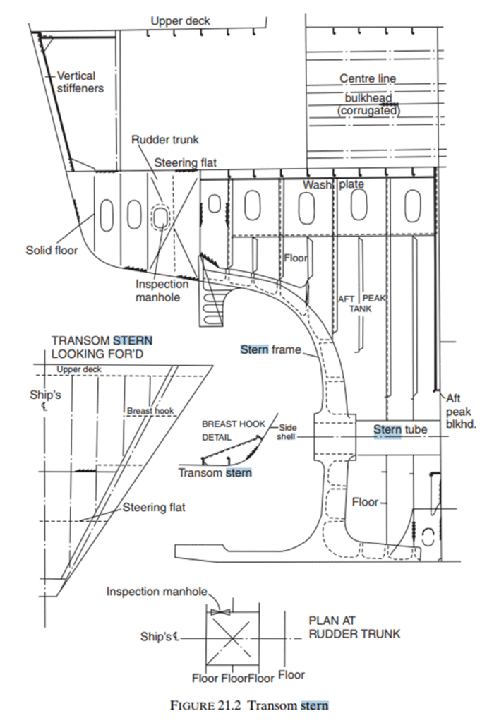
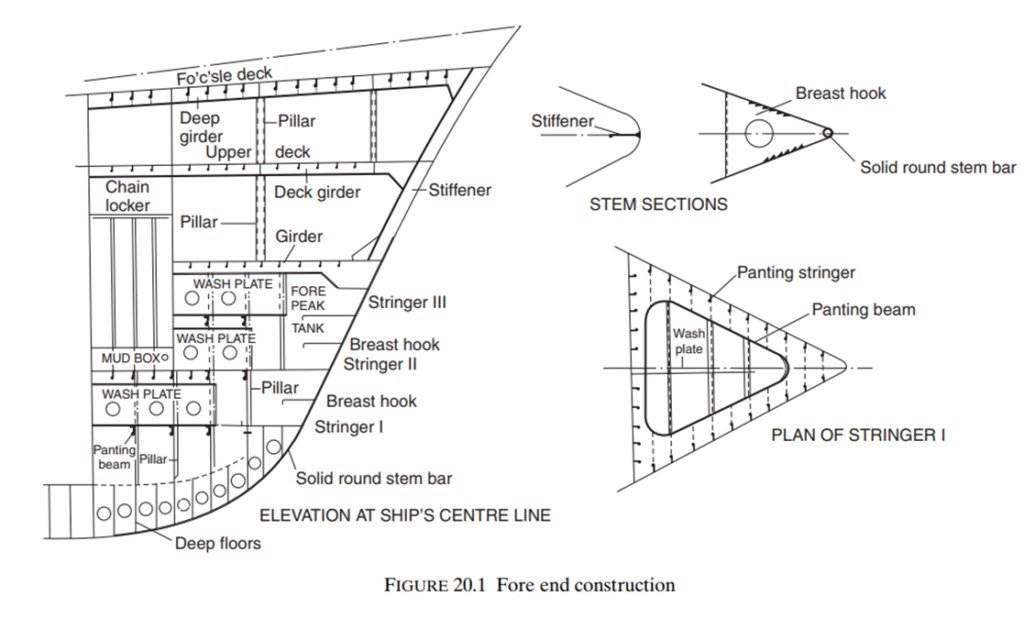
1. Draw and explain forward construction of ship
2.squat effect
3.tie rod bolt broken, identify and procedure for removal and replacement
4. Reverse power trip diagram and explain
5.ism and lastest amendments
1/17/2024
Class 1
Class 1 Group Oral
MR David & Mr Rui
1.Inclining Test
2.Squat Effect
3.Viscotherm
4.SG block Diagram,Regulations,Healthy steering System
5.EG,how to test black out scenario.
6.LO emulsification
Time:1215-1350
Verdict: 2 out of 3 candidates Passed.
Class 2
Examinar, David and rui
1.stern tube seal arrangement explain.
2.dry Dock seal replacement.
3.preparential trip.how you maintain the ship without this safety device.
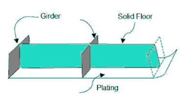
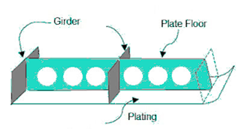
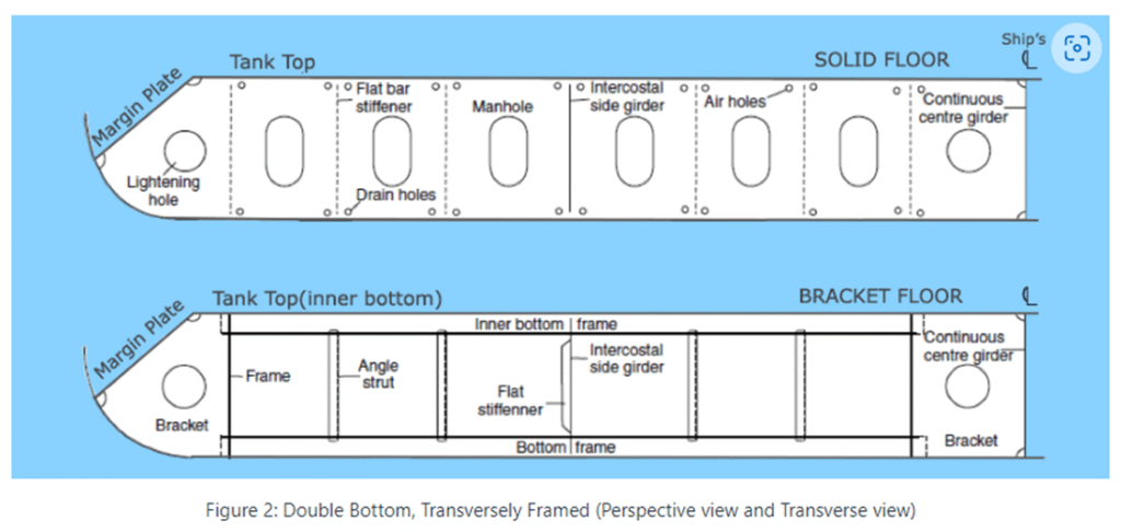
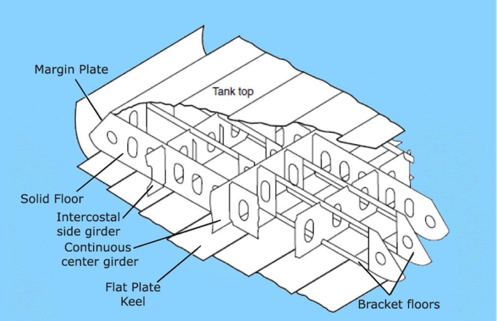
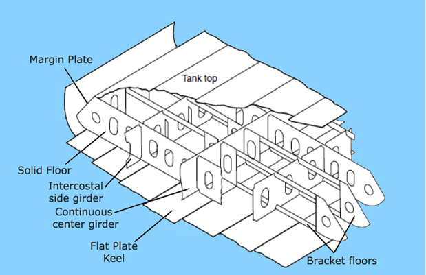
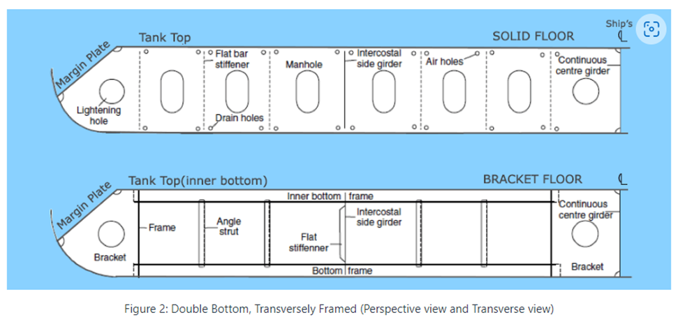
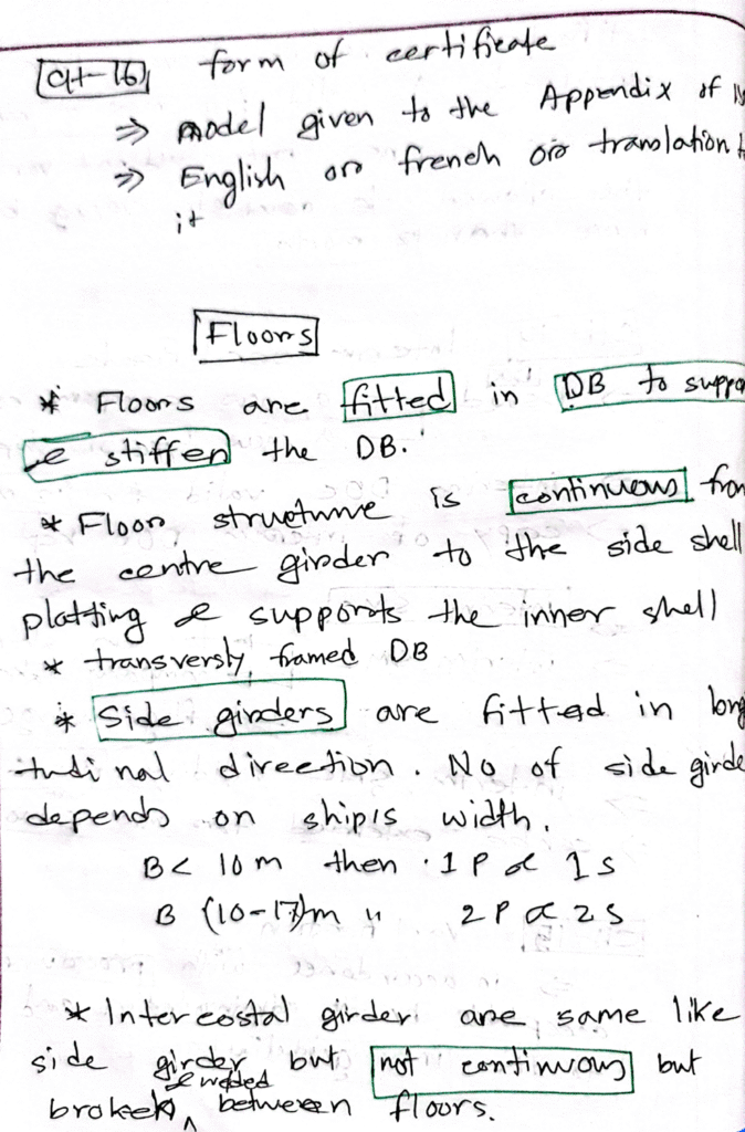
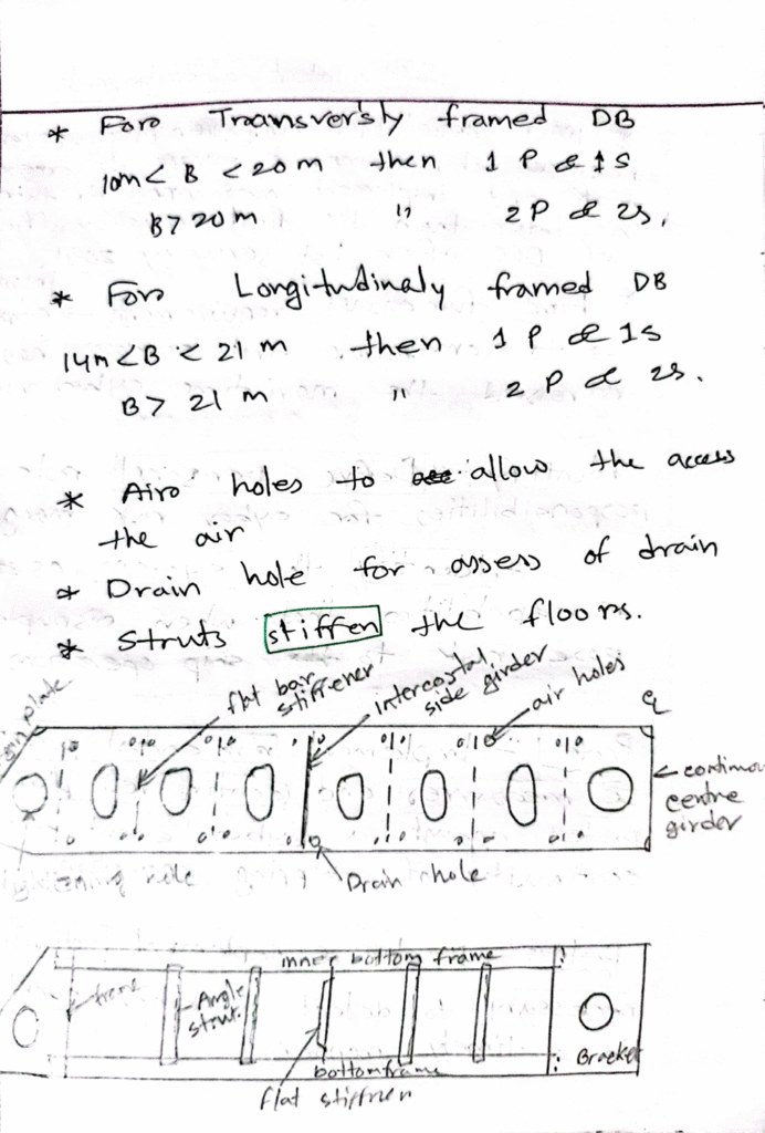
4.floor construction, and differences.
5.Annex 1.
6.Annex 2
7.Annex 5.
8.Marpol violation.
,,,one assignment..topic one
,,, one fail.
,,other one assignment 3.
1/19/2024
Class 1
Mr. David sir
Time:0200pm
Passed Alhamdullilah
1.Draw and explain ship floor construction .
2.Draw centrifugal pump with mechanical seal.Explain sealing arrangement
3.Draw air starting valve explain working principle.
4.Effect of starting air valve leaking.
5.Starting air line explosion reason.
6.Air bottle solas regulations
7.Draw high lift safety vv explain ,what surveyor checks on safety vv.
8.Draw Viscosity controller and explain effects of low or high viscosity
9. Squat effect cause and corrective action.
1/24/2024
Class 2
Mr. Rui and Mr.David
location: MPA
Class
1. Old Piston overhaul and sketch
2. Tube L.O cooler Sketch and checks and troubleshooting of defects
3. AVR sketch and explanation and faults can be faced in AVR, action and follow up action
4. Single Phasing
Sketch, action, troubleshooting, Follow up action and how will u improve ur system as per SMS.
5. ANNEX 6
6. Settling tank cleaning in DD
Class 2
1 uws
2air bottle regulation
3.ums regulation
4isps
5 drawing liner and explain over hauling procedure and report to office, corrective and preventive measure
6T/C drawing , cause of surging , and action
Preferential trip drawing and explain
1/26/2024
Class 1
Class 1
2nd attempt
1 sea experience
2 ism chief engineer duty
3 steering gear block diagram
4 tubular cooler diagram
Class 1
2nd attempt
1 Isps
2 ism
3 steering gear block diagram
4 tubular cooler diagram
Viscothum sketch & working principle
Emulsification
1/31/2024
Class 01 oral exam
Time:11:30 to 14:00
1. Sketch boiler safety valve and explain
2. CII
3. cold ironing
4. Marpol annex 6
5. MLC
6. Explain sea service and tell incindents onboard
7. steering gear regulation
8. how to keep steering gear healthy
2/07/2024
Class 2 Second attempt
8.30am to 10.30am
David
1.UMS REGULATIONS ELABORATE ANSWER. apart from solas requirement, u need to mention about all alarms boiler, me, ge, talk about autostart of emergency
2. FLOOR IN SHIP CONSTRUCTION AND EXPLAINATION WITH DRAWING
3.FIREMANS OUTFIT WITH ALL SPECS.
4.BOILER DP CELL,WATER CONTROL AND FAULTS .
REASON FOR DP CELL NOT INDICATING EVEN IF NO WATER INDICATION IN GUAGE GLASS
5.MARPOL VIOLATIONS AND FINES
6.HOW WILL U TRAIN UR FIRST TIME THIRD ENGINEER FOR GENERATOR OVERHAUL.
6.ISM CERTIFICATION EXPLAIN IN DETAILS
2/14/2024
Class 2 group oral
Time : 0900 hours
1. Mlc
2. battery room ,
3. co2 system maintanance
4. annex 6
5. ows drawing ,
6. boiler valve ,
7. annex 1 mepc 107 49
Class 2 group oral
Time : 14 00
1. Draw STP & certification annex 4 regulation
2. ISM certification in detail
3. MLC certification in detail
4. UMS regulation in detail
5. Crankshaft DEFLECTION explain full in detail
2/15/2024
Class 1
Class 1 online oral
Time : 1000
1. As a chief engineer what you check in fire inventory
2. sketch fwd construction and explain in details
3. Sketch manoeuvre diagram ahead and astrean moment explain in details
4. ISM latest edition and ISM documentation
5. annex 6 (SEEMP,EEDI,EEOI,CII)
6.MLC
2/16/2024
Class 1
Examiner Rui
Time 9:30
Result fail
1.Annex vi brief
2.Annex 1…crossing question regarding standard discharge connection for annex 1 and 4
3.liner digrame
4.oily water separator digram and sample point digrame
5.piston diagram.
6.During crankcase inspection u will find white metal in crankcase.as chief engineer how will u proceed.
7.MEPC 107(49)..
2/21/2024
Class 2
Group oral
Surveyor – David and Ruu
Location – MPA tower
Time – 0900 to 1010 hours
Questions of David –
1. Earth fault drawing and how you will detect one on board.
2. Maritime security requirements on board your vessel.
Questions from rui –
1. How you will carry out crankcase inspection and how you will train your junior to take crankshaft deflection.
2. Which regulation and maintenance for c02 bottles.
3. Congratulations rod bolt failure and what corrective or preventive measures you will take.
Class 2
Group oral -Class 2
Surveyor – David and Rui
Location: M tower
Time: 1030 to 1200 hrs
1. Earth faults elaborate with diagram.
2. Maritime security explain.
3. Crankshaft deflection –2 stroke engine.
4. Conrod failure, consequence and corrective measure- elaborate for 4 stroke engine.
5. Risk assessment explain with matrix.
6.ISM certification
Class 2
Group oral
Surveyor – David and Ruu
Location – MPA tower
Time – 0900 to 1010 hours
Questions of David –
1. Earth fault drawing and how you will detect one on board.
2. Maritime security requirements on board your vessel.
Questions from rui –
1. How you will carry out crankcase inspection and how you will train your junior to take crankshaft deflection.
2. Which regulation and maintenance for c02 bottles.
3. Con rod bolt failure and what corrective or preventive measures you will take.
2/28/2024
Class 1
David
Earth lamp diagram + cross questions
Sewage treatment plant diagram+ explanation
Zakir:
Load line convention
Statutory certificate + class certificates explain.
Annex 6 latest amendment.
3/02/2024
Class 2
Group oral -Class 2
Surveyor – David and Rui
Location: M tower
Time: 09:30 to 11:00
1.Earth lamp diagram + cross questions
2.Sewage treatment plant diagram+ explanan
3.steering gear block diagram+Emergency steering +cross questions
4. Conrod failure, consequence and corrective measure- elaborate for 4 stroke engine.
3/06/2024
Class 1 oral
Mng: 0930- 1100
Battery room regulations, PLS ans non sparking fan blades.
ISM DOCUMENTATION , DUTIES, LATEST AMENDMENT full details
Marpol violations and fines
Marpol pollution action and reporting procedures
TIE ROD SKETCH , TIE ROD SLACK AND BROKEN , CAUSES, FUNCTION OF TIE ROD, PROCRDURE TO REMOVE BROKEN ROD, RUNNING ENGINE WITH BROKEN ROD PROBLEMS,prevention action.
REPORTING IN PMS
CIC FOR FIRE AND SAFETY
Class 1. 6th march, 1400 Hrs
Examiner: Mr David & Rui
(1) Squat effect, cause, remedy, action
(2) Earth lamp drawing, how to find fault, details with lots of cross questions.
(3) ISM certification, latest ammendments, lots of cross questions.
(4) IACS and classification society recognised by MPA.
(5) Draw TEV and describe working principle
(6) X – head bearing failure indication, cause, action to be taken.
3/08/2024
Class 1 ORAL
Surveyor – David and Rui
Location: ISC (For Assignment)
Time: 1400 to 1500
08/03/24
Note: On my first attempt (06.03.2024), my answers was not sufficient for Class 1 Standards.
So, they gave me ASSIGNMENT on 8th.
QUESTIONS ASKED:
1. Battery room regulations,
PLEASE MENTION non sparking fan blades instead of non-metallic ONLY. Battery room light location.
2. ELABORATE ISM DOCUMENTATION, CERTIFICATION , DUTIES, LATEST AMENDMENT in details
3. MARPOL VIOLATIONS, FINE & PENALTIES,
Marpol pollution action and reporting procedures with Case studies, Reporting channel TO SINGAPORE MPA
4. TIE ROD SKETCH , TIE ROD SLACK AND BROKEN , CAUSES, FUNCTION OF TIE ROD, PROCRDURE TO REMOVE BROKEN ROD, RUNNING ENGINE WITH BROKEN ROD PROBLEMS,prevention action.
REPORTING IN PMS
5. CIC, themes of CIC, PERIOD, LAST 2 YEARS CIC WITH DETAILS OF TOPIC, MoU’s & their REGION & Members, What going to happen in 2024 in CIC with focused topics.
3/11/2024
Class 1
Class 1 2nd attempt online
Mr.David
Questions:
Load line convention
Earth lamp + insulation meter.
Sewage plant( annex 4 requirement)
Marpol annex 1 violation
Cic fire safety
3/13/2024
Class 1 group oral.
Date- 13/3/2023
Time- 8.30 to 10.15
Examiner- David & Rui
Questions-
1. Earth fall drawing, fault detection procedure.
2. STP Drawing, Discharge reg of untreated sewage from holding tank.
3. Crosshead bearing failure- indications, causes & action.
4. Ism certification.
Class 1. 13th march, 1400 Hrs
Examiner: Mr David & Rui
(1) Emergency circuit diagram draw with all safties,working principle,possible causes not come on load,how to convince psc.
(2) Sterntube seal change on drydock,how to check shaft alignment.
Above 2 question was asked by Mr rui..then he left..
After that a long disscussion carried out by Mr david which include the topics
1.Erm
2.marpol violation
3.incident onboard
4.Mlc
5.sea carrier
Class 1 group oral.
Date- 13/3/2023
Time- 1400 to 1600
Attempt 1 st
Examiner- David & Rui
Questions-
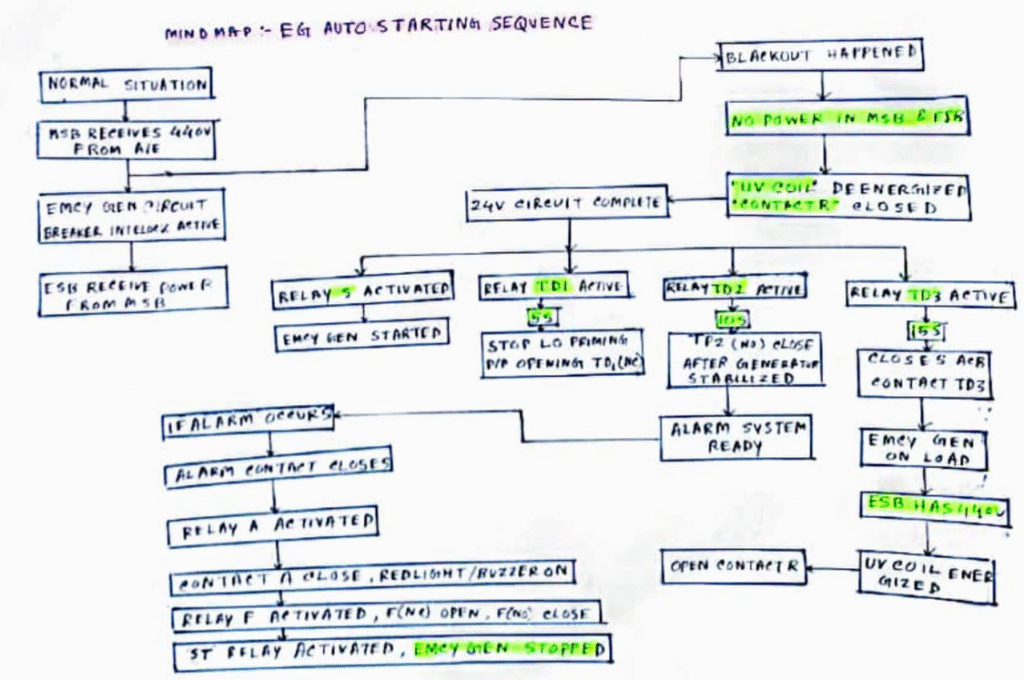
1. Emergency generator auto circuit diagram and explain.
2. Stern tube changing procedure with all safeties and after changing what all to check.
3. In front of psc if emergency generator doesnt start how to satisefies him and wha
3/15/2024
Class 1
Surveyor : David Sir
Face to face
Date : 15.03.2024
Time : 1000 hrs to 1200 hrs
Ques :
1. Tie Bolt
2. Battery room Regulation
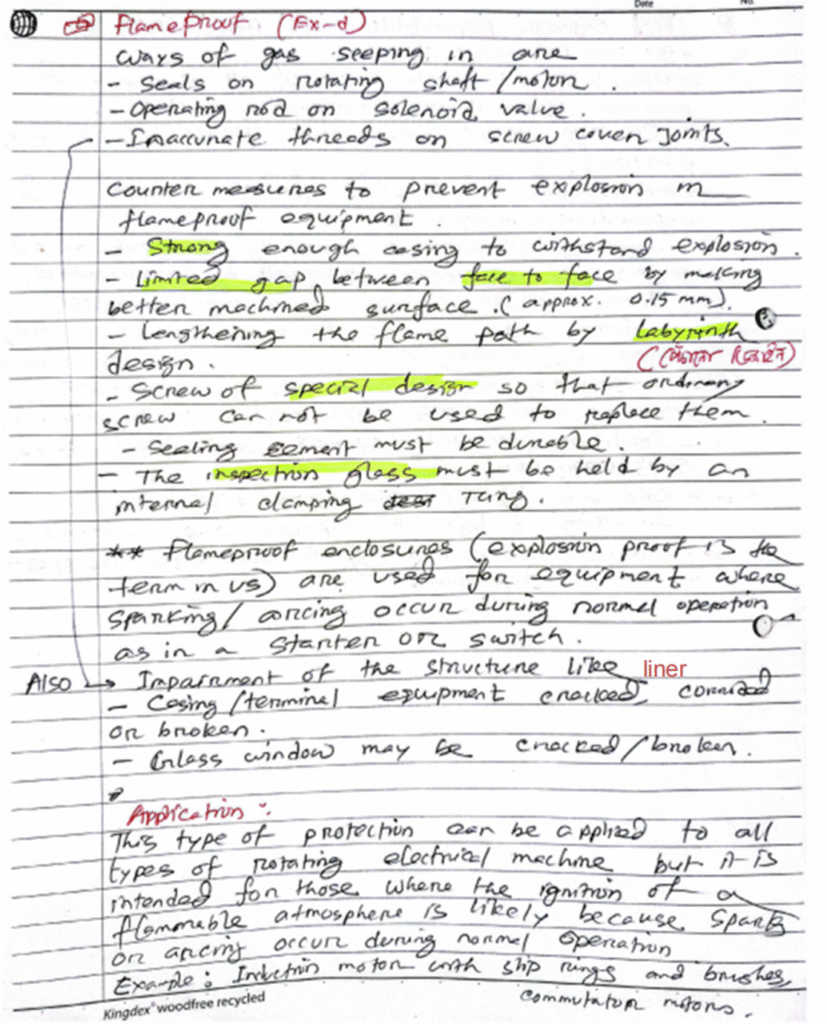
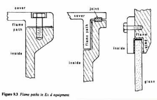
3. EX-e
4. Ism, certification, CE ism duty, ism Compliances
5. CIC (2022, 2023, 2024)
6. Mou (paris, tokyo)
7. IACS
8. Marpol Violation, reporting channel, onboard Marpol Awareness
9. Boiler Safety Valve
10. Earth Fault.
3/19/2024
Class 1 , Rui, 10.30-11.30,Pass
1)annex 6 CII,seemps,eexi,eedi
2)S/T seal dd renewal-Preparation as C/E ( not the notes of usual small things)
3)detection of xhd brng failure in a running engine as a c/e
I work in the maritime digital industry ashore….so lot of discussion on EU ETS,new methods to reduce CIi, Fuel EU maritime, MEPC 81, Fuel optimisation, MLC harrasment, weather optimisation etc.,
3/20/2024
Class 1
Lube oil emulsification…cause ..root cause ..preventive action.. reporting to office..
Sewage treatment plant drawing…regulations…sewage holding tank capacity..(class approval discharge rate..)
Steering gear block diagram…
5 years class certification and survey…
Garbage management plan..
All marpol violations and fines
20.03.2024
Class 1
Class 1
Time 0200
David & rui
1. Ford. Construction & floor
2. Viscosity controller
3. Ism details
4. Isps
5. Annex v
6. Reverse power trip
7. Tie bolt
Rui
1.sturn tube seal replacement at dry dock
2. Black smoke during Leaving singapore port
Class 1
1400 hours
Surveyors Mr. David and Mr. Rui
They notice ur dress and hairs and beard. They pointed this thing to my friend.
1. Collision bulkhead diagram
2. Floor arrangement diagram n explain
3. Tie rod diagram and explain in detail
4. Reverse power trip explain n draw
5. Inclination test. In detail. Requirements and procedure.
6. Annex 4 and Annex 5
7. Black smoke 🚬. Looking for governor in the answer in control part.
8. Lube oil properties.
9. Stern tube seal renewal in dry dock. As ce what will u do.
3/27/2024
CoC class-1
Examiners Mr David and Mr Rui
Manouvering(not diagram)
Stern tube
Psc emgcry gen
Cic
-Water oil in starting air system of main engine consequences and what to do to prevent it
-Emgcy gen starting diagram
*Emgcy gen Starting circuit was asked only to one guy
* Due to current accident of baltimore
* Mr,David ws quite emphasising on manouvering and reasons how can it b effected,, PMS to follow and what all you will do to avoid it all
* Stern tube renewal preparation for dry dock rui wants to hear Dry dock specs specifically in preparation
* Water oil carrying over to manouvering system is all related to first quesn only
– Psc quesn of emergency gen as usual one but only this is you shd make your own scinerio if ship in port at anchor, gen starts or not, if not start trouble shooting, still doesn’t start and u don’t have spares then speak of reporting to company and request for dispensation where class will give you CoC to get pass the detention if emergency generator doesn’t start
– Rui says showing records is not enough ship will surely detain
4/08/2024
Class 1
Exam: class1
Online oral
Result: pass
Following topics with , drawing, explanation , relevant cross questions and regulations
emcy generator circuit diagram
Boiler safety VV , setting procedure
Boiler survey
ME Piston
ME Unit ohauling
STP , maintenance
Annex 4
4/17/2024
Class 1
17 April 2024
Class 1
Face to face
0830 to 1010
Davit and Rui.
4 candidates.
1. ME slowdown safety devices.
2. Crank case relief valve sketch and elaborate operation and materials.
3. OMD sketch, operation, test and maintenance.
4. Crank case explosion causes & action.
5. High voltage system sketch
6. Emergency generator starting circuit drawing+ explain and Emergency generator solas regulation, what action if no load infront of PSC.
7. ISM certification and latest amendments.
8. Risk assessment matrix
9. As a CE how you will guide 3E to major overhaul of AE
Class 2
1.What will happen if you dont do maintenance of air staring valve
2. Draw staring air valve
3. Too much cross ques and discussion on starting air valve and explotion
4. LO emulsification
5. Annex 4 and draw STP
6. Annex 5
7. TEV draw and air condition regulation
8. ISPS and security requirement in ship
4/24/2024
Class 1
0830 to 0945
Davit and Rui.
4 candidates.
1. Preparation for PSC inspection
2. Crosshead bearing failure indication reason n actions
3. DD seal renewal
4. DD specification
Class 1 oral 08:30, 24.04.2024
PSC/FSC inspection
Emergency Steering Regulations
Cross-head bearing failure indications,causes,actions, prevention. (Mr Rui wanted to hear about ISM procedure on reporting)
Lots of discussions on these……
4/26/2024
Class 1
Online 3rd attempt.
0730 to 0830 IST
Davit. Pass.
1. MLC 2006
2. Additional safety Measures for bulk carrier
3. Strboscopic effect
4. Crankcase explosion and draw CC door relief valve.
4/30/2024
Class 1
1000-1200 hrs David
1. Crankcase relief valve drawing and explanation.
2. OMD drawing and explanation
3. ME alarm and safety device
4. Reverse power trip and working principle
5. Ism certification and ism latest amendment.
6. Crankcase explosion causes and prevention.
7. Scavenge fire prevention and action.
By the grace of Almighty allah passed.
5/08/2024
Class 1
1)seemp+cII
2)EG dia +explain
3)ISPS
4)DRY DOCK -complete
5)sterntube seal change -preparatiin
6)Psc inspection
7)statuatory
8)how u maintain yr ship maneuverability as a ce .
9)high voltage drawing and explain with control.
Class 1
8 May 2024
CoC 1 First attempt
0830H – 1030H
1)seemp+cII
2)EG dia +explain
3)ISPS
4)DRY DOCK -complete
5)sterntube seal change -preparatiin
6)Psc inspection
7)statuatory
8)how u maintain yr ship maneuverability as a ce .
9)high voltage drawing and explain with control.
10) Emergency fire pump regulation and what do PSC checks.
For assignment
1) HVI drawing with automatic controls
2) As a C/E, how do you prepare PSC. in flow chart/mind map/ words
3) As a C/E how you comply with ISM and improvement
Class 2
Alhamdulillah Passed.
1. Annex -5 details. Garbage management plan and record book details. So many cross questions.
2. ISPS in details
3. CO2 flooding system drawing, Regulations, Co2 room maintenance, Training junior about Co2 system.
4. S/T sealing drawing and Seal renewal in drydock.
5. Emergency generator regulations
6. Which type of garbage can / can’t burn.
7. MLC in details
8. PSC inspection. Black out procedure.
9. Cll and Seemp details.
10. Cross head bearing failure during ME running conditions. As a CE what is your action, how you will identify, failure causes .
1 group. 4 candidate’s.
2 pass , 1 assignment, 1 next time
after 30 minutes thay separated two groups 2 with rui. Other two David.
5/15/2024
Class 1 group Oral
Surveyor: Mr. David and Mr Rui
Questions:
1. Ballast water management system in details.
2. Annex – IV, sewage treatment plant drawing maintenance, checks, consequences of blower failure.
3. Emcy generator auto starting diagram, starting sequence, psc inspection – fail to start and recovery procedure.
4. As a C/E, instructions to 3E regarding generator major overhaul.
5. As a C/E, Dry dock preparation in details.
Class 1 group oral
Surveyors: David & Rui
Time: 14:00-15:30 hrs
1. In Water survey
2. Reverse power trip
3. Switchboard safety device
4. Crosshead bearing failure details
5. CO2 maintenance
5/16/2024
Class 1 oral
1000-1200 hrs
Online
2nd attempt
Surveyor : Mr David sir
1. Online oral terms and conditions
2. Crosshead bearing survey
3. Annexe 5
4. Reverse power trip and drowning
5/21/2024
Class 2
Class 2 oral
1330-1530 hrs
Surveyor : Mr David sir & Rui sir
1st attempt
1. Tie rod sketch and tightening, failure reason in detail.
2. Isps in detail
3. Flame proof light drawing and detail discussion
4. Maritime convention
5. Ship marking regulations
6. Ship grounding in detail
Class 2
Class 2 Oral
10:30-12:30
Surveyor: Mr David & Rui
1st Attempt group oral
1. Reverse power trip drawing and explanation.
2. Main switch board protection devices,
3. Sewage treatment plant drawing
4. Sewage shore connection and size,
5. Your ship is going to Dry Dock, how to prepare for HFO settling tank cleaning
6. Boiler High lift safety valve drawing
7. How many IMO conventions are there,
8. During departure Singapore, your junior engineer report one of the main engine unit exhaust temperature high, what is your action,
9. Risk assessment matrix.
Class 1 Oral
21.05.2024
1530pm-1730pm
1.Statutory certificate 5 yearly renewal.
2.Air bottle regulation.
3.ISPS
4.Annex 5
5.Incinerating Onboard
6.Onboard Equipment Certificates
7.Crosshead bearing failure, Cause, Action.
8.Dry Dock
9.As C/E what job to be present physically at DD
5/23/2024
Class 2
Co2 sketch
Detail explains
How to train Junior while Inspection
How to operate co2 if fire in Engine room
Isps in detail
Battery room Regulation
Checks maintenance
Hydrolic door and Regulation
Type of door
Different between weather tight door and hydrolic door
Crankcase Inspection
Wt if u find any debris??
How to close report as 2nd Engineer
Class 2 oral
1330-1515hrs
Face to Face
1st attempt
Surveyor : Mr David & Mr Rui
1. Crankcase relief valve(drawing with so many cross questions including material,Why this material used,how flam trap works etc)
2. Flame proof light drawing & cross ques.
3. Battery room regulations(cross)
4. NDT test,procedures,types,dry dock how they carried out
5. Con rod bolt(failure,cause,preventive measures)
6. How to train 3E for AE decarb including documentations
7. Grounding
5/29/2024
Class 2
MEO- 2 oral
1400-1530 hrs
29.05.24
Surveyor : Mr David & Mr TEO
1st attempt, SMA
IG details with reg.
Liner calibration elaborately ( cause, precaution, procedure, post action)
Preferential trip sketch, principle, how to avoid.
FO settling tk cleaning bf DD ( planning, procedure, report, inspection, survey)
ME single unit exhaust temp high ( cause, action, remedy, conclusion)
Class 2
MEO Class – II Oral
Date – 29.05.2024 Group – 3 Result – 2 Pass + 1 Assignment
Examiner – Mr. Rui & Mr. Teo
Initial introduction of our group all sailing on tankers
1. What are the regulations related to inert gas system onboard. What are the regulations related to IG system.
2. ME liner calibration, Why needed, When needed, How to take, troubleshooting, finding the root cause, corrective action, preventive action. ISM must include.
3. How to do HFO settling tank cleaning in dry dock, why, then he said what are the preparations prior going to dry dock. He wanted defect list & dry dock job list stage level starting.
4. Drawing – Preferential trip, cross questions, dashpot working, then SOLAS regulations of PMS(Power management system)
5. Then pass to Mr. Teo – Duty engineer calls you 3 AM vessel at sea that ME one unit exhaust temperature deviation is more than 50 degree what are your actions. Plenty cross questions by Mr. Teo as well as Rui. ISM procedures, causes, actions, how to troubleshoot etc etc.
6/05/2024
Class 1
05.06.2024
Examiner: Rui
Class 1
Result: 1 pass, 1 assignment.
Draw explain Air con system and regulations.
LO emulsification. As a CE explain causes and action.
As CE handle PSC for black out scenario.
Vessel in high traffic area and black out happen. Action as CE.
Stern tube seal renewal in DD.
Class 2
Today class 2 orals@2 pm Mr. Rui and Foo Nan
1.crankshaft deflection all details starting from procedure to reporting and if clearance is exceed limit how u will renew
2. MLC and certification procedures
3. OWS MEPC 107(49) including shore discharge dimensions
4. CII and EXII details
5. ISPS certification and all details including procedures to get certificate and how you will get certificate
6. Risk assessment matrix
7. Exhaust valve material
6/07/2024
Class 2
Individual Oral (2nd attempt)
Time: 0930~1040
Result: Alhamdulillah Passed
Examiner: Mr. Rui
1. St. Gear block diagram+explanation
2. St. Gear Solas regulations
3. Vsl in manouvering has
Blackout,recoveryprocedure, contingency plan
4. MLC certification,objective parts
5. M/E Cyl. liner calibration procedure in details
6. Marpol Annex 6 chapter 4 all regulations.. later asked on IMO GHS strategy..CII details
7. Newly promoted 3E A/E major o/h guidance procedure in details as 2E.
Class 1
Assalamu alaikum
By the grace of almighty today i have cleared my coc 1.
I had assignment on the following topic:
1.Accommodation Ac sketch and explain, major components, regulatory requirements
2.Psc onboard, asked you to carry black out test but emergency power didn’t come on load with in 45s, action as CE and causes
3.Vessel at sea and blackout happens what is your action as CE
Class 2
Individual Oral (2nd attempt)
Time: 11:30-13:00
Result: Assignment
Examiner: Mr. Rui
Class : 2
1. St. Gear block diagram+explanation.
2. St. Gear Solas regulations.
3. Vsl in manouvering has
Blackout,recoveryprocedure, contingency plan.
4. MLC certification,objective parts.
5. M/E Cyl. liner calibration procedure in details.
6. Marpol Annex 6 chapter 4 all regulations.
7. Starting air line explosion cause, remedy, record keeping all details.
8. Air conditioning unit everything including marpol, solas & MLC regulation.
6/12/2024
Class 1
Class: 1
Group Oral at SMA
Examiner: Rui
12.06.2024/10:00
1. Crosshead Bearing Failure – Indication, cause, action
2. Blackout test with PSC
3. Blackout at heavy traffic area – Action as CE
4. CIC
5. ESP – how to Prepare for annual Survey.
6. Boiler water level -DP Cell drawing.
7. Emcy gen Auto starting Ckt Diagram
8. Duty As CE
Class: 1
Group Oral at SMA
Examiner: Rui & Fu nan chu
12.06.2024/14:00hrs
Result: 1 Assignment 2 fail
1. A/E pump roller broken, reason, corrective action.
2. FO properties with limit.
3. ESP
4. Condition of assignment, Load line survey.
5. FWD construction OF ship
6. Dry dock.
7. Heavy traffic area blackout. Action as C/E.
6/15/2024
Group oral -Class 2
Surveyor – Rui sir
Location: SMA
Time: 14:00 to 1600
19/06/24
Explain CIC
Ism with certification
Annex 6 full certification
Crankcase inspection
How u Assist chief engg in manouverbility
Risk assessment matrix
ME one unit Exhaust temp high during traffic channel
6/19/2024
Class 1
Class: 1
Group Oral at SMA
Examiner: Rui
19.06.2024/10:00hrs
Result: 1 Assignment 2 fail
1. How to maintain vessel maneuverability?
2. Draw Air conditioning plan and regulations?
3. EG auto circuit? Psc black demonstrations?
4. Types of lubrication?
5. DP cell and working principle
6. Types of lubrication
7. Ism details with certifications
8. Risk assessment matrix
Group oral -Class 2
Surveyor – Rui sir
Location: SMA
Time: 14:00 to 1600
19/06/24
Explain CIC
Ism with certification
Annex 6 full certification
Crankcase inspection
How u Assist chief engg in manouverbility
Risk assessment matrix
ME one unit Exhaust temp high during traffic channel
6/26/2024
Class 2
Group oral – class 2
Surveyor – Rui sir and Devid sir
Location- SMA
Time – 0930 to 1100am
-C/C relief door drawing and explanation
-2 stroke engine lub oil properties
-flame trap
-sms in detail
-reverse power trip
-how will u assist c/e in manoevribility
-black in heavy traffic action as a 2/E
-ISM
Lub oil properties for 2 stroke engine
Class 2
Group 2 orals, rui sir and David sir, Sma
Time 11:30 to 13:00 hrs.
-Regarding the fire fighting equipment how you can do to avoid fire in engine Room as 2 engg. Elabrate
– main engine safeties and omd diagram and function.
– cold ironing
– Emergency fire pump regulations. Not building pressues and action.
– annex 4 explain
– mepc 107 -49
– cii and all certificate.
– fire line diagram with elabrate together with addition bilge and fire pump.
– marpol all regulations.
– sms in details.
-2 guys passed.
7/03/2024
Class 2
Alhamdhulillah passed
Coc -2, Time : 0830 hrs
2nd attempt, 1 person
Surveyor: Mr David
1.Main engine safety devices, Trips and alarms.
2.Fwd construction drawings and why this is kept so strong
3.Co2 system and description
4.Reverse power relay draw and describe its operations
5.ISM details
6.CO2 maintenance
Class 2
Coc -2, Time : 0130 hrs
2nd attempt, 1 person
Surveyor: Mr David
1.Draw Earth lamp and explain.
2.Fwd construction drawings and why this is kept so strong
3.Reverse power relay draw and describe its operations
4.Draw Boiler safety and explain.
5.How you Assist chief engineer during maneuverability.
7/04/2024
Class -2 face to face
Surveyor -mr David and Rui
1.lub oil types
2.reverse power trip
3.boiler safety valve
4.risk matrix
5.how u train 3/E Ae overhaul
7/08/2024
Class 1
Class 1 , online
2nd attempt,
Surveyor david:
1.ONLINE TERMS AND CONDITIONS.
2.VERY DETIALED ELABORATE DETAILS AND ROOT CAUSE INCLUDE FUEL OIL PROPERTIES ANALYSIS AND PREVENTIVE ACTIONS
DURING MANOUEVRING AT RESTRICTED CHANNEL OF DAALI INCIDENT. (I am from synergy company).
3.CIC 2024
4.BOILER DP CELL LEVEL CONTROLLER SKETCH.
repeated qsns from last attempt except daali root cause report.
Class-1, Online
2nd attempt
Surveyor: Mr. David Tham
Time: 1200~1305
Result: Pass
1. Terms & condition of online examination.
2. Draw position 1 & position 2 as per load line.
3. Condition of assignment of freeboard.
4. Black out in high traffic area, action as chief engineer.
5. Explain Drydocking preparation, procedure in detail as C/E.
6. Five yearly Statutory survey and certificates.
7. Draw and explain reverse power relay.
07/31/2024
Class 1 (Shahidul sir)
Lo emulsification… action as ce
– Ism code
– steering gear redundancy how to ensure
– eexi, cii, nox – annex 6 ch 4
– emcy gen not getting connected in main supply failure
08/21/2024
Class -1 Oral (Kamrul sir)
Examiner: David & Rui
Candidates-3
Time: 0930AM
Result: Alhamdulillah All passed
Questions:
1. Draw High Lift Boiler safety valve
2. Safety valve survey & SOLAS requirement
3. ISM
4. CIC 2024
5. LO Emulsification
6. Annex 6 Chapter 4
7. Blackout in heavy traffic area, duties as a CE
04.09.2024
Class 1
04.09.2024 Class-1
David and rui
Attempt -1
Result-passed with assignment
Total appeared- 3 guys (2-pass with assignment, 1-fail)
1) x head bearing failure. Identify, causes n action as CE
2) Reverse power sketch & explain.
3) MLC certification issuing procedure.
4)steering failure, cause and action.
5) cic . What is next cic for this year
6)what is criminal penalty if ships make accident or pollution
7)main switch board safety.
8) stern tube drawing all seals and explanation
11.09.2024
Class 1
Time: 11:00
Total: 4person
Verdict: 3 pass & 1 assignment
Examiner: david & rui
Questions:
1. High voltage instruments (mandatory to carry onboard in high voltage ship).
2.reverse power relay. (drawing, explanation and if happened reverse power trip on-board as a chief engineer what is your action).
3. details about cii, eedi, eeoi, eexi. (the whole energy efficiency and carbon emissions reduce Process).
4.ism certification in details.
5.Mlc certification.
Class 1
Time: 2pm
Verdict: 2 pass
Question:
1. Inclining experiment
2. Sewage treatment plant draw and explain with regulation
3. SW splashing on motor
4. Dry dock preparation
And mny mny cross questioning.
18.09.2024
Class 1 oral
18th September 2024
Group Oral
3 candidate
Examiners: David & Rui
Questions:
1. Viscosity controller & related cross question
2. Cofferdam entry (Enclosed space entry Details)
3. Black out demonstration in front of PSC
Em DG not starting. Causes & Course of action.
4. Stern tube seal renewal in DD details.
1 passed, 1 assignment, 1 fail.
25.09.2024
Class 1 oral online
25th September 2024
Examiners: David
Questions:
1. Viscosity controller & related cross question
2. Cofferdam entry (Enclosed space entry Details)
3. Black out demonstration in front of PSC
Em DG not starting. Causes & Course of action.
4. Stern tube seal renewal in DD details.
Pass
Class 1 orals online
25th September.
Examiner: David
Lifeboat SOLAS regulations
AVR and Reverse power sketch.
ISPS code
02.10.2024
Class 1 orals
Date: 2nd October 2024
Time: 2pm
Questions asked:
1) what are the statutory certificates to carry on ship, how is it being issued and explain in detail.
2) emergency blackout procedure in front of psc, causes and action
4 candidates, All passed!!
Class 1:
Class 1 orals
Date: 2nd October 2024
Time: 0330pm
Rui took orals, I was alone at that time.
David was taking orals to class 2 guy.
Questions asked:
1) Solas regulations of IG system
2) IG system drawing and explanation
3) Emcy Gen Auto Circuit drawing
4) Difference btw Tie Breaker and Circuit breaker
5) Actions as a CE if EDG not starting automatically during PSC inspection
6) Difference between Statutory certificates and Mandatory Certificates
Assignments:
1. Statutory and Mandatory Certificates
2. Difference btwn Tie breaker and Circuit breaker
Submitted on 03rd, 0930am.
Along with the assignment explanation,
1. Stern tube seal renewal at dry dock.
2. Wat are the clearances taken
3. ISM code
Finally: Passed 👍.
Thank you everyone 🙏
16.10.2024
Class-1 Oral
Date: 16/10/2024
Time: 09:30
01) viscotherm drawing+ cross question+ potential failure+ malfunction root cause: action as a c/e
02) viscotherm & other- control valve cross question+
03) fo heater cross question
04) st sealing drawing+ function of seal+ lots cross question
05) st allignment checking procedure+ cross question
06) ac regulation for SOLAS & mlc
07) ac drawing
08) annex 4 details + annex-4 certification+ related lots cross question
Class-1 Oral
Date: 16/10/2024
Time: 02 PM
Single face to face
Alhamdulillah Pass
01) What’s the things you have study explain elaborately.
02) Draw and explain accommodation ac plant and explain the regulatory requirements.
03) ISM certification
04) 5 yearly statutory certificates with supplementary.
05) sketch & explanation stern tube sealing arrangement.
06) How to keep your ship maneuverable?
07) Blackout in heavy traffic area action as CE.
23.10.2024
Class-1 Oral
Date: 23.10.2024 (0930 am)
4 candidate- 3 pass 1 assignment
1. Inclining experiment in detail. Focusing on preparation before carrying out experiment.
2. STP diagram. Focusing on all necessary installation checked by psc. To confirm STP optimum performance
3. How to check healthy steering, causes of steering gear erratic functioning
4. Steering gear regulations
5. How to train 3rd engg for AE overhaul. Concentrating SMS(ISM), planning for overhaul, assessment of 3rd engg to overhaul AE. Monitoring safety, and documentation.
6. Emergency steering gear trying out frequency. And why 1ce in 3 months.
26.02.2025
Class-1 Oral
Date 26/02/2025
Time:09:30
Examiner : David and Rui
Class 1 orals
1 st Attempt Face to face
1) How you will prepare you ship for PSC inspection? In detail
2) As a CE how you assess manoeuvrability of your ship.
3) Risk assessment in detail.
Result -pass
28.03.2025
Class-1 oral
Date 28/03/2025 at 1000hrs.
CLASS 1
Surveyor: Mr. Zahir
Online second attempt.
1. How to take Main engine performance in details with parameters checked.Draw various performance curves and explain how to read the curve. Calculation of power and SFOC.Factors affecting SFOC.How does air temperature and sw temprature affect performance. What has economiser to do with performance, explain in details.
2. Draw Accomodation Air conditioning diagram and explain all the regulations of AC and ventilation in details.Checks to be carried out on accomodation AC.
3. Condition of assignments of freeboard, define all regulations,position 1&2 draw and dimensions for all engine room opening, dimensions of vent heads and ventilatiors. Explain protection of crew in details.
4. Draw ows diagram as per mepc 107(49).Explain and demonstrate how to carry out OWS operation while PSC inspection.
5. Different types of survey. Statutory and mandatory certificates with survey required. Which authority issues which certificate, explain in detail.
Result: Pass
15.04.2025
Class-2 Oral
Class 2 orals : Examiner Mr. Rui:, time: 02:00 PM
1.Drawing of Turbocharger
2.Marpol Annex 6
3.Responsibilities of a second engineer
4.Caustic embrittlement
5.Steering gear regulations.
6.Con.rod bolt failure reasons.
23.04.2024
Class 1
Time: 0900 AM
1. Isps in details certification/enhance maritime security)
2. Tie rod drawing and explanation
3. Vapor compression cycle and explain
4. Main engine bearing clearances : only how to take
30.06.2025
Class 1 – oral
30/06/2025
Class 2
Face to Face
Mr Rui
1. Who give COC (which pillar of IMO)
2. STCW full form and adopted date
2. Difference between management level and operational level coc
3. Draw boiler water controller
4.what is PID principle , what I controller,P controller and D Controller
5.what is STA . How will u assess juniors.
6.What is PMS
7.how will u plan and overhaul a piston.he wants more about documentation
8.what is Risk assessments and Risk assessment matrics
9.Type of ship Sailing .
10. Dual fuel system explain in detail
11. Viscosity controller and it’s working
Result : pass
30.06.2025
Class 2 oral
30/06/2025
Class 2 . Face to face
Mr. Zahir, at SP
1. Crank shaft deflection of ME in detail starting from Safeties
Draw and indicate the dial gauge mounting location
– Draw n show measurement point
– Draw the C/S deflection form . With Details in the form like ship name , trim , draft etc
– What are the factors to be considered prior taking C/S deflection
– How will you match dial gauge temp to the temp of the webs ?
– How will you know that your readings are correct or How will you analyse the measurements after it has been taken.
2)Draw Boiler manhole door .
Why Elliptical? Why not circular ?
Boiler survey
3 ) Piston overhauling procedure ( only interested in how will you separate the Crown from the piston)
4 ) draw MEPC 107 (49)
How will you demonstrate it for PSC ?
Wht will you do if Automatic stopping valve start leaking?
5 ) why is it called MLC 2006 ?
How to obtain MLC Certification detailed procedure ?
Thank you .
01.07.2025
Class 2 – Oral
Class II.
Face to face 2nd attempt
Mr Rui.
Questions.
1. What do you know about MLC.
2. What do you know about term reserve Power.
3. prefresional trip drawing and explain how you as a second engine minimise this.
4. Crankshaft deflection 2 stroke main engine.
5. Types of lubrication.
6. Psc on board emergency fire pump not making desire pressue what to do as a second engineer.
7. Draw fire line system drawing.
Result: Pass.
Thankyou everyone.
01.07.2025
Class-2 Oral
Class 2 2nd attempt face to face
M tower, Mr, Rui
1st July, 12:30 pm
1. what is STCW ( one should know the name of STCW 8 chapters )
2. Risk Assemment and explain the matrix and everything
3. Piston overhauling, according to him answer at the managment level and organise your answer ( plan , implement and execute the job ) , He don’t want to listen the procedure of piston overhauling.
4. PSC is onboard and emergency fire pump don’t have enough pressure on deck, what will be your action as a 2nd Engr
5. draw the block diagram of steering gear
6. Stern tube sealing arrangement, how u will renew the seal in dry dock.
Result Pass
01.07.2025
Class-01 Oral
Alhamdulillah today pass 2nd attempt
Class 1
1- co2 system diagram and its maintenance ,regulations
2- foam system maintenance certificatition.
3- fiver year satuary and class certification
4- viscotherm diagram and viscosity not maintaining causes.
5-condition of assignment
02.07.2025
Class-01 Oral
Class 1
Mr. Rui
1.IG Regulations and operations.
2. Emergency generator automatic starting system, black out procedures and PSC checks and power not obtained in front of the psc Surveyor, actions for CE.
3. Marpol Annex 6 chapter 4 details
4. 5 yearly Class and statutory survey.
5. IG scrubber overboard line crack during cargo operations, what is CE actions?
03.07.2025
Class-2 Oral
03/07/2025
Class 2 . Face to face
Mr. Zahir, at SP
1. Crank shaft deflection of ME in detail starting from Safeties
Draw and indicate the dial gauge mounting location
– Draw n show measurement point
– Draw the C/S deflection form . With Details in the form like ship name , trim , draft etc
– What are the factors to be considered prior taking C/S deflection
– How will you know that your readings are correct or How will you analyse the measurements after it has been taken.
– explain gauge reading
– reason for horizontal deflection
2)Draw Boiler manhole door .
Why Elliptical? Why not circular ?
Boiler survey
3) draw MEPC 107 (49)
How will you demonstrate it for PSC ?
Wht will you do if Automatic stopping valve start leaking?
4) why is it called MLC 2006 ?
How to obtain MLC Certification detailed procedure ?
5) vapour compression cycle
TEV fails what happen
Safety arrangement in cylinder head
Define degree of super heat
Define saturation temp
Result ——-pass
Thank you .every for supporting for clearing exams ,
Keep on we will do