About Engr. Shafiul Bari

Shafiul Bari is a seasoned Marine Engineer with extensive experience in ship design, maintenance, and marine propulsion systems. With a deep technical knowledge of ship engineering and a passion for advancing maritime technology, Shafiul shares practical insights and expert advice to help marine professionals and enthusiasts better understand the complexities of ship systems. Through his website, he aims to bridge the gap between technical theory and real-world application, fostering a community of informed and skilled maritime engineers. When not immersed in ship engines and technical manuals, Shafiul enjoys exploring the latest innovations in marine technology and mentoring aspiring marine engineers.

Testing of Emergency Generator

The testing of ship’s emergency generator is done every week (as part of weekly checks) by running it unloaded to check if it starts on battery mode. The hydraulic start is done every month to ensure that it is working fine. Also every month automatic start of generator is also done to check its automatic operation and to see whether it comes on load.

Procedure for Battery Start

1. Go to the emergency generator room and find the panel for emergency generator.
2. Put the switch on the test mode from automatic mode. The generator will start automatically but will not come on load.
3. Check voltage and frequency in the meter.
4. Keep the generator running for 10-15 min and check the exhaust temp and other parameters.
5. Check the sump level.
6. For stopping the generator, put the switch in manual and then stop the generator.

Procedure for Hydraulic Start


1. Out the switch in manual mode as stated above and check the pressure gauge for sufficient oil pressure.
2. Open the valve from accumulator to generator.
3. Push button the spring loaded valve and the generator should start.
4. Check voltage and frequency.
5. Keep the generator running for 10-15 min and check the exhaust temp and other parameters.
6. Check the sump level
7. For stopping, use the manual stop button from the panel.
8. After stopping the generator, pressurize the hydraulic accumulator to desired pressure.
9. Close the valve from accumulator to generator.

Procedure for Automatic Start

For automatic start, we know that there is a breaker which connects Emergency Switch Board (ESB) and Main Switch Board (MSB); and there is also an interlock provided due to which the emergency generator and Main power of the ship cannot be supplied together.
2. Therefore, we simulate by opening the breaker from the tie line, which can be done from the MSB or the ESB panel.
3. After opening the breaker, the emergency generator starts automatically with the help of batteries and will supply essential power to machinery and pumps connected to ESB.
4. For stopping the generator, the breaker is closed again and due to the interlock the generator becomes off load.
5. Now again put the switch to manual mode to stop the generator.
6. Press stop and the generator will stop.

List of equipment connected to the Emergency Power source on the ship-

§ Emergency Lighting
§ Emergency steering motor
§ Emergency fire pump
§ Emergency Bilge pump

§ Foam pump

§ Emergency air compressor
§ Necessary machines to start one generator
§ Emergency alarms

§ Fire detecting and fire alarm
§ Engine room ventilation fan
§ Communication

§ Bridge control console
§ Cargo control console
§ Engine room control console
§ Battery charger for emergency generator
§ Battery charging panel
§ The rescue boat, life raft & Lifeboat Davit
§ Navigational and signal lights
§ Navigational Equipment

 § GMDSS radio console
§ The compressor of breathing apparatus
§ Watertight door
§ Remote control Valves

Links : https://shipfever.com/emergency-generator-on-ships/

Emergency Generator SOLAS Requirement – memorization technique:

Emergency Power Source Types

  • Generator
  • Accumulator battery

Generator Requirements

  • Prime Mover: Driven by a suitable prime mover with independent fuel supply
  • Fuel Flashpoint: Not less than 43°C (closed cup test)

Location and Installation

  • Above the uppermost continuous deck
  • Away from machinery space
  • Behind the collision bulkhead
  • Main switchboard should not interfere with emergency power supply, control, and distribution

Operational Capabilities

  • List and Trim: Operable with a list of up to 22.5° and a trim of up to 10°
  • Duration:
    • Cargo ship: 18 hours
    • Passenger ship: 36 hours
  • Starting Temperature: 0°C (heating arrangement required for lower temperatures)
  • Automatic Start: Within 45 seconds after main power failure
  • Failure Indication: To be given in ECR if emergency generator fails to start

Starting Arrangements

  1. Primary: Battery
    • Always fully charged
    • Capable of 3 consecutive starts
  2. Secondary: Pneumatic or hydraulic
    • 3 consecutive starts within 30 minutes
    • First start within 12 minutes

Transitional Emergency Power

  • Type: Accumulator battery
  • Function: Provides power automatically to emergency lighting during main or emergency power failure
  • Voltage Maintenance: Within 12% above or below nominal voltage during discharge

Accumulator Battery as Emergency Source

When used as the main emergency power source:

  1. Carry emergency load without recharging
  2. Maintain voltage within 12% of nominal during discharge
  3. Automatically connect to emergency switchboard upon main power failure
  4. Immediately supply power to emergency lighting

SOLAS REQUIREMENTS FOR EMERGENCY GENERATOR

.emergency generator

.emcy generator    .egr

The requirement for emergency power onboard the ship is detailed in SOLAS chapter 2-1
SOLAS CH: II-1 / Part : D / Reg : 43 & 44

The emergency source of electrical power may be either a generator or an accumulator battery for essential services under emergency conditions.

Where the emergency source of electrical power is a generator, it shall be

§ Driven by a suitable prime mover with an independent supply of fuel having a flashpoint (closed cup test) of not less than 43°C

§ Emergency generator and emergency switchboard of the ship should be located above the uppermost continuous deck, away from machinery space, behind the collision bulkhead.
§ The main switchboard of the ship should not interfere with supply, control, and distribution of emergency power.
§ Emergency source of power should be capable of operating with a list of up to 22.5° and a trim of up to 10 °
§ Emergency generator should be capable of giving power for the period of 18 hours for the cargo ship and 36 hours for the passenger ship.
§ Emergency generator should start at 0°C and if temperature fall below this then there should be heating arrangement.
§ Emergency generator should come on load automatically within 45s after the failure of main power supply.
§ If the emergency generator fails to come on load the indication should be given to ECR.
§ Emergency generator should have two different starting arrangement
§ Primary may be the battery, should fully charge all time and capable of providing 3 consecutive Start.
§ Secondary may be pneumatic or hydraulic, capable of providing 3 consecutive starts within 30 min, and 1st start within 12 min.

§ In addition to emergency generator a transitional source of emergency electrical power should be provided,

→ The transitional source of emergency electrical power shall consist of an accumulator battery suitably located for use in an emergency. It shall operate without recharging while maintaining the voltage of the battery throughout the discharge period within 12% above or below its nominal voltage. The battery capacity should be sufficient . Capable of supplying power automatically to emergency lighting in the event of failure of either the main or emergency source of electrical power

→ Where the emergency source of electrical power is an accumulator battery, it shall be capable-

.1 carrying the emergency electrical load without recharging. It shall maintain it voltage 12% above or below its nominal voltage while discharging.

.2 it should also capable of automatically connecting to the emergency switchboard in the event of failure of the  main source of electrical power; and

.3 immediately supplying power to emergency lighting

SOLAS

Chapter II-1 : Construction – Structure, subdivision and stability, machinery and electrical installations

Part – E Additional requirements for periodically unattended machinery spaces

UMS requirements: ums regulation

.umsr

.ums regulation

.ums requirement

SOLAS chapter 2-1 part E which is  called – Essential requirements for any unattended machinery space

(UMS)

regulation 46 to 53,describes the UMS regulations

Regulations 46 General

Regulations 47 Fire Precaution

Regulations 48 Protection against Flooding

Regulations 49 Control of Propulsion Machinery from Navigation Bridge

Regulations 50 communication

Regulations 51 alarm system

Regulations 52 safety system

Regulations 53 Special requirements for machinery, boiler and electrical installations

Regulation 46 General

  1. The arrangements provided to ensure that the safety of the ship in all sailing conditions, including manoeuvering, is equivalent to manned machinery spaces.
  2. Machineries should be maintained to ensure that the equipment is functioning in a reliable manner. Inspection and routine tests are Carried out to ensure continuous reliable operation of machineries.
  3. Every ship shall be provided with documentary evidence, proving its fitness to operate with periodically unattended machinery spaces.

Regulation 47 Fire Precaution

1.  Arrangement should be provided on UMS ship to detect and give alarm in case of fire.

a.  In the boiler air supply casing and uptake.

b. In scavenge space of propulsion machinery.

2. In engines of power 2250 Kw and above or cylinders having bore more than 300mm should be provided with oil mist detector for crankcase or bearing temperature monitor or either of two.

Regulation 48: Protection against Flooding

  1. Bilge well in UMS ship such that the accumulation of liquid is detected at normal angle of heel and trim and should also have enough space to accommodate the drainage of liquid during unattended period.
  2. Where the bilge pumps are capable of being started automatically, means shall be provided to indicate when the influx of liquid is greater than the pump capacity or
  3. when the pump is operating more frequently than would normally be expected.

Where automatically controlled bilge pumps are provided, special attention shall be given to oil pollution prevention requirements.

Regulation 49: Control of Propulsion Machinery from Navigation Bridge

  1. The propulsion machinery should be able to be controlled from bridge under all sailing conditions. The bridge should be able to control the speed, direction of thrust, and should be able to change the pitch in case of controllable pitch propeller.
  2. Emergency stop should be provided on navigating bridge, independent of bridge control system.
  3. Indicators shall be fitted on the navigation bridge for:
    1. propeller speed and direction of rotation in the case of fixed pitch propellers; or
    1. propeller speed and pitch position in the case of controllable pitch propellers.
  4. Propulsion machinery orders from the navigation bridge shall be indicated in the main machinery control room or at the propulsion machinery control position as appropriate.
  5. The remote operation of the propulsion should be possible from one location at a time; at such connection interconnected control position are permitted.
  6. The number of consecutive automatic attempt which fails to start the propulsion machinery shall be limited to safeguard sufficient starting air pressure.
  7. It shall be possible for all machinery essential for the safe operation of the ship to be controlled from a local position, even in the case of failure in any part of the automatic or remote-control systems.
  8. The design of the remote automatic control system shall be such that in case of its failure an alarm shall be given.

Regulation 50 Communication

A reliable means of vocal communication shall be provided between the main machinery control room or the propulsion machinery control position as appropriate, the navigation bridge and the engineer officers’ accommodation.

Regulation 51 Alarm System

  1. An alarm system shall be provided indicating any fault requiring attention and shall:
    • be capable of sounding an audible alarm in the main machinery control room or at the propulsion machinery control position, and indicate visually
    • the alarm system shall have a connection to the engineers’ public rooms and to each of the engineers’ cabins
    • alarm system shall give an audible and visual alarm on the navigation bridge for any situation which requires action by or attention of the officer on watch.
    • It Shall activate the engineers’ alarm if an alarm function has not received attention locally within a limited time.
  2. The alarm system shall be continuously powered and shall have an automatic change-over to a stand-by power supply in case of loss of normal power supply.
  3. Failure of the normal power supply of the alarm system shall be indicated by an alarm.
  4. The alarm system shall be able to indicate more than one fault at the same time and the acceptance of any alarm shall not inhibit another alarm.

Regulation 52 Safety systems

A safety system shall be provided to ensure that serious malfunction in propulsion machinery or boiler operations, which presents an immediate danger, shall initiate the automatic shutdown

Regulation 53 Special requirements for machinery, boiler and electrical installations

  1. The main source of electrical power shall be such that:
    • In the case of loss of the generator in operation, a stand-by generator of sufficient capacity will automatically start to allow propulsion and steering and to ensure the safety of the ship.
    • automatic restarting of the essential auxiliary machineries need to be provided.
    • If the electrical power is normally supplied by more than one generator simultaneously in parallel operation, in the event of loss of one generator power, the other ones continue operation without overload to allow propulsion and steering, and to ensure the safety of the ship.
  2. Where stand-by machines are required for other auxiliary machinery essential for propulsion, automatic change-over devices shall be provided.
  3. Automatic control and alarm system
    • The control system shall be such that the services needed for the operation of the main propulsion machinery and its auxiliaries will automatically start.
    • An alarm shall be given on the automatic change-over.
    • A centralized control position shall be arranged with the necessary alarm panels and instrumentation indicating any alarm.
  4. Where internal combustion engines are used for main propulsion a system shall be given to keep starting air pressure at the required level

Regulations:

Types of Survey:

.types of survey

.type of survey    .tos

  1. Initial Survey
  2. Annual Survey
  3. Intermediate Survey
  4. Renewal Survey
  5. Additional Survey
  6. Docking survey
  7. In water survey
  8. Special survey

Initial Survey: 

The initial survey is held before the ship is put in service or when a new device is added to an existing ship, and the relevant certificate is issued to that ship. The initial survey includes a complete inspection, with tests, when necessary, of the structure, machinery and instruments to ensure that the requirements relevant to the particular certificate are compiled with structure, machinery and ships instruments are fit for the service and for voyage.

Annual Survey: 

Annual survey is conducted once a year with leeway of 3 months. It is required by all the ships. A surveyor inspects all the equipment (LSA, FFA) and everything else during annual survey. Example- Load Line Survey

An annual survey allows the administration to verify the condition of ship and its equipment whether it is being maintained in accordance to the regulations. It consists of a certificate examination, a visual examination of the ship and its equipment, and certain tests to ensure that their condition is being properly maintained according to conventions. The content of each annual survey is given in their respective guidelines. It should also include a visual examination to confirm that no unapproved modifications have been made to ship and its equipment

Intermediate Survey: 

Generally, it is conducted after 2.5 years of previous survey certification or after the third anniversary date of the appropriate certificate and should take place after one of the annual surveys.

The intermediate survey is inspection of items appropriate to particular certificate to ensure equipment are working in good conditions and they are seaworthy.

When specifying items of hull and machinery for detailed examination, due account shall be taken of any continuous survey schemes that they are in a satisfactory condition and they are fit for service and voyage.

Renewal Survey:

 It is conducted before the appropriate certificate is renewed but not exceeding 5 years. The renewal survey should consist of an inspection, with tests when necessary, of the structure and machinery spaces to ensure that relevant certificates are compiled with the equipment checked during survey. All certificates, record books, check list, recording manuals and other documents are also checked during Renewal survey.

Additional Survey:

 Whenever accidents occur to a ship or any damage is caused which affects the safety or integrity of ship or the efficiency or completeness of its equipment, the master or owner should make a report as soon as possible and submitted to the administration, the nominated surveyor or recognized organization responsible for issuing that particular certificate should then initiate an investigation/inspection to determine whether a survey, as required by the regulations applicable to the particular certificate, is necessary. This additional survey, should be such as to confirm that the repairs and any renewals have been effectively made and the ship and its instruments are fit for ship and for further voyage.

Docking Surveys

Ships are to be examined in drydock at intervals not exceeding 2½ years twice in 5 years period. And the interval between two docking survey should not exceed 36 months. At the drydocking survey, particular attention is paid to the shell plating, stem frame and rudder, external and through hull fittings, and all parts of the hull particularly liable to corrosion and chafing, and any unfairness of bottom.

In-water Surveys

The Classification Society may accept in-water surveys in lieu of any of the two dockings required in a five-year period. The in-water survey is to provide the information normally obtained for the drydocking survey. Generally consideration is only given to an in-water survey where a suitable high resistance paint has been applied to the underwater hull.

Special Surveys

The special surveys are carried out at intervals of 5 years. A more thorough examination is required at the special surveys. The shell plating, stern-frame and rudder are inspected. The holds, peaks, deep tanks and double bottom tanks are cleared and examined. The tanks are tested for water-tightness. The bilges and tank top also are inspected. Thickness measurement of hull plating is also carried out and recorded. Special survey hull requirements are divided into four ship age groups as follows:
1. Special survey of ships – five years old
2. Special survey of ships – ten years old
3. Special survey of ships – fifteen years old
4. Special survey of ships – twenty years old and at every special survey thereafter
In each case the amount of inspection increases and more material is removed so that the condition of the bare steel may be assessed.

Difference Between Hard Iron and Soft Iron

Definition

Hard Iron: Hard iron is iron that is difficult to demagnetize once magnetized.

Soft Iron: Soft iron is iron that is easily magnetized and demagnetized with a small change of magnetic field.

Material

Hard Iron: Hard iron is a hard magnetic material.

Soft Iron: Soft iron is a soft magnetic material.

Magnetization

Hard Iron: Magnetized hard iron cannot be easily demagnetized.

Soft Iron: Magnetized soft iron can be demagnetized.

Applications

Hard Iron: Hard iron is used as permanent magnets.

Soft Iron: Soft iron is used as electromagnets.

What is Soft Iron

.soft iron

Soft iron is iron that is easily magnetized and demagnetized with a small change of magnetic field. Soft iron does not refer to the soft nature of the metal; in fact, soft iron is also a hard, metallic iron. But unlike in hard iron, the magnetic domains shifted towards the direction of a magnetic field can be shifted back to the initial state. In other words, it is reversible. But the returned magnetic domains will align in a random manner.

Figure 2: An Electromagnet

Soft iron is used in the production of electromagnets. Therefore, the field can be turned on and off. An electromagnet can be made by coiling a wire around a piece of soft iron and connecting the two ends of the wire to a battery. When the current is running through the wire, this system acts as a magnet. Then the domains of the soft iron bar align with the direction of the applied field and, the intensity of the magnetic field is increased by several magnifications.

Non-destructive testing

.ndt test

.non destructive testing

Nondestructive testing (NDT) is the process of inspecting, testing, or evaluating materials without destroying the serviceability of the part

Visual inspection inspect for high splatter, undercut, bad stop start point, surface crack.

1) Surface inspection

  • Magnetic particle
  • Liquid penetrant

a) Magnetic particle

  1. Testing magnetic fields to locate surface discontinuities in magnetic materials.
  2. When the magnetic field encounters a discontinuity, the flux lines produce a magnetic flux leakage
  3. Because magnetic flux lines don’t travel well in air, magnetic particles are applied to the surface of the part will be drawn into the discontinuity,
  4. Use of a Yoke to generate magnetic field

b) Liquid penetrant test

Step 1 – Precleaning of the Surface

The 3 spray cans (aerosol) are provided for this test. First one is named cleaner.  The technician sprays the cleaner to the test object and then cleans the surface with non-used rag or cloth.

Step 2- Application of Penetrant

In the second step, the technician applies penetrant spray can to the surface which is in sharp red color. The technician needs to wait for 5 to 15 minutes depends on test procedure.

Step 3- Removal of the Excess Penetrant Liquid

In the third step, the technician removes penetrant liquid from the surface by rag or cloth and uses back and forth rubbing to clean the surface. No red color should be visible after cleaning.

Step 4 – Application of Developer

In the fourth step, the technician takes the developer spray can and agitates it and then sprays to the surface. Then he waits for 10 minutes. In this time, the defect will be visible

Step 5 – Evaluation / Interpretation

In the fifth step inspector evaluates the test result 

2) Internal inspection

  • Radiography
  • Ultrasonic most frequently used test methods

a) Radiographic method

  • Exposing a test object to penetrating radiation so that the radiation passes through the object being inspected and a recording medium(film) placed against the opposite side of that object.
  • With both, the radiation passing through the test object. causing an end effect of having darker areas where more radiation has passed through the part and lighter areas where less radiation has penetrated.
  • Use of x-ray or gamma ray

b) Ultrasonic method

  • Ultra-high frequency sound is injected into the part being inspected and if the sound hits a material with cracks, discontinuity some of the sound will reflect to the sending unit and can be presented on a visual display.
  • By knowing the speed of the sound through the part and the time required for the sound to return to the sending unit, differences shows place of crack.
  • Thus, able to find likely area of discontinue by the darker area

Dezincification

.dezincification

Dezincification selectively removes zinc from the brass alloy. It leaves behind a porous, copper-rich structure that has little mechanical strength. An in-service valve suffering from dezincification has a white powdery substance or mineral stains on its exterior surface. 

Reason for dezincification

Zinc is a highly reactive metal in galvanic series ranking. Zinc has a very weak atomic bond relative to other metals. Zinc galvanic polential is -.76V where for Copper it is +.34V. Simply, zinc atoms are easily given up to solutions with certain aggressive characteristics. During dezincification, the more active zinc is selectively removed from the brass, leaving behind a weak deposit of the porous, more noble copper-rich metal.

Factors which cause increased rates of dezincification are Copper-zinc alloys containing more than 15% zinc are susceptible to dezincification. high temperature, high chloride content of water, and low water speed.  Adding tin, Ni and Al in the alloy can reduce dezincification. Dezincification occurs in pump casing, impellers and in valves

Graphitization

.graphitization

 Graphitization is a microstructural change that occurs in carbon or low-alloy steels exposed to temperatures of about 425–550°C for several thousand hours.

It causes the metal to weaken and be susceptible to cracking failures. The steel tends to break down to form iron and carbon (graphite); carbon will migrate to the material’s grain boundaries forming graphite nodules, which causes the metal to become brittle, losing strength, toughness, creep resistance, and ductility.

Creep resistance is solid material’s ability to resist “creep”

Creep: tendency of a material to slowly deform over a long period of exposure to high levels of stress.

METALS USED FOR DIFFERENT SHIP PARTS

.ship building material .ship building material  .sbm  .ship material .shipbuilding material

Ships are made up of a variety of different metals and metal alloys. Different metals will suit different part requirements best. Below are some of the most common ship parts and the metals they are composed of.

SHELL PLATING

Shell plating is typically made of rolled plain steel of grades D or E. During the steel ship hull construction, shell plating, creates a water-tight barrier on the bottom and sides of the ship. It typically consists of several curved and flat steel plates, welded together.

SUPERSTRUCTURES

The superstructures are the part of the boat that is built up above the deck. An example of this is seen on any cruise ship. The superstructures of ships are now commonly made with aluminum alloys. This allows for the ship to be lighter as a whole than if the superstructures were made of steel, and the ship’s center of gravity is lower.

WATERTIGHT DOORS

Watertight doors are doors constructed on both sides of a watertight bulkhead. These doors are typically made of cast steel and prevent water from entering the ship. It is important that steel is used because the doors need to be capable of withstanding high pressures, if they are poorly made then a ship could flood.

STERN FRAME

The stern frame supports the tailshaft of the rudder and the propeller. In old ships, the frame used to be welded to the hull. The frame is typically fashioned from steel plates with plate sides that are stiffened for added support. In order to prevent it from corroding, it is heavily coated.

RUDDER PINTLES

Rudder pintles refer to the bolt/pin that attaches the rudder to the ship. In the past, brass pins in hardwood frames were used. But upon the introduction of steel, it was found that a stainless steel pintle is stronger and cheaper than its brass counterpart. The basic functionality of the pintle is similar to that of a door hinge.

PROPELLERS

Ship propellers are usually constructed by a copper alloy, like brass, to withstand the corrosive effects of saltwater. They are specifically designed to prevent cavitation which occurs when bubbles of water vapor collide with the propeller and create small dents. Propellers generate the propulsion force of the ship by turning in a fan-like motion.

Marine propellers are manufactured from corrosion-resistant materials as they are made operational in seawater which is a corrosion accelerator. The materials utilized for making marine propellers are an alloy of stainless steel and aluminum. Other popular materials employed are alloys of nickel, bronze, and aluminum, which are 10~15 % lighter than other materials and have higher durability.

Also

Cast steel is used in parts of rudder, stem and stern

Forged steel used in anchor, chain, rudder shaft

Non-ferrous metal – Aluminium used in compass area, superstructure, boats, copper nickel alloy (pipes)

Plastic and wood used in interior equipment and boats.

Steel production method

.steel production method

.steel prod method

De-oxidationProcess 
KilledSteel has been completely deoxidized (oxygen removed) during liquid stage, by adding agent (aluminium) before casting, so that there is practically no evolution of gas during solidification.
Semi-killedSteel is mostly deoxidized steel, however carbon monoxide leaves blowhole (porosity) distributed throughout the ingot. It is commonly used for structural steel with a carbon content between 0.15 – 0.25%. Structural steel is formed by “rolling” process, the process closes the porosity.
RimmedSteel has little or no deoxidizing agent added.
CastingHeating Iron Ore to liquid stage, add-in required agent, then pour the molten
metal into mold to form shapes.
ForgingHeating the steel into Austenite stage (plastic forms), then use mold to forcefully pressing / hammering (with high force) the metal into shape.
RollingHeating steel plate / ingot(steel block) into Austenite stage (plastic forms), then use roller to forcefully pressing the steel plate / ingot into shape.

Heat Treatment Process

.heat treatment process   .htp

Heat TreatmentProcess
AnnealingHeat steel to recrystallize stage (>900oC), then cool it in furnace at very
slow rate
, to improve it’s ductility and higher elongation rate.
NormalizingHeat steel to recrystallize stage (>900oC), then cooled it in atmosphere, to
make it less ductile, however improve tensile strength & toughness
QuenchingHeat steel to recrystallize stage (>900oC),then cooled it rapidly using liquid
(oil or water), as the carbon molecule unable to escape in time, it change into
Martensite stage. Martensite steel is very hard, however brittle.
TemperingAfter quenching the steel, it is re-heated to below recrystallize stage (700 –
800oC)
, then cooled it in atmosphere, to make it regaining part of its’ ductility
and tensile strength.

Hardening of steel:

.hardening of steel    

.steel hardening  .wh

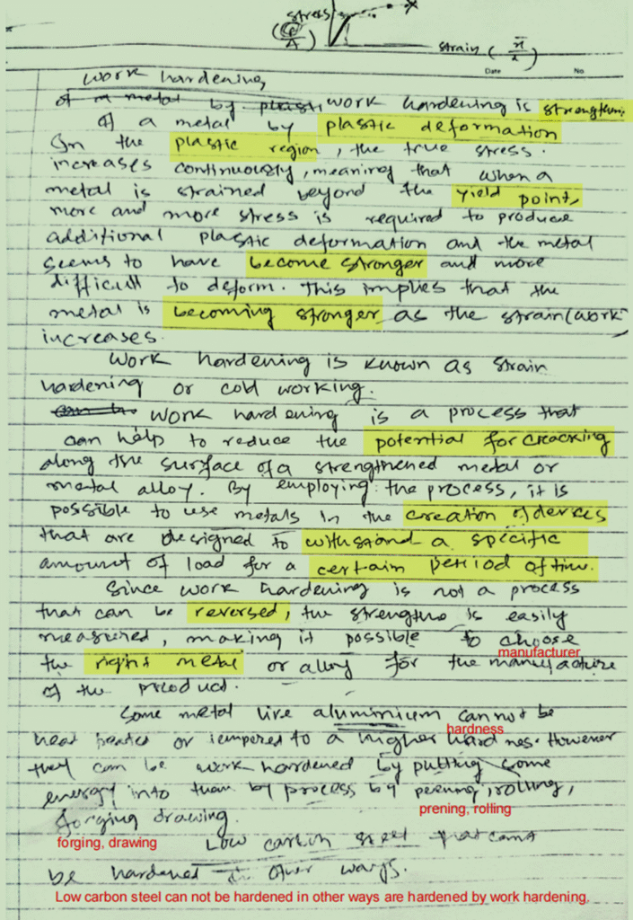
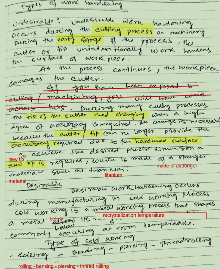
Work Hardening

Work hardening is strengthening of metal by plastic deformation.

→ Case Hardening

Case Hardening
Method
Process Description
Flame HardeningHeat the steel very rapidly with flame (>900oC), then quench (cooled rapidly) in water.It create a Martensite case on steel surface. Suitable for steel of carbon content 0.3-0.6%. The process cause steel to deform, and required tempering to restore steel core toughness.
CarburizingHeat the steel very rapidly with flame (>900oC) , then quench (cooled rapidly) in oil. It create a High Carbon Steel case on steel surface. Suitable for steel of carbon content 0.1-0.3%. The process cause steel to deform, and required tempering to restore steel core toughness.
NitridingHeat the steel to approx. 500 – 600oC, then keep it in ammonia gas filled enclosed case. Nitride case will form on steel surface.
The process cause very little steel deformation. Do not required further heat treatment for core material.
CyanidingHeat the steel to approx. 900oC, then keep it in a bath of sodium cyanide salt. Then wash off the salt with water or oil. The process causes little steel deformation and do not require further heat treatment for core material. However, the salt is poison to human.

Where case hardening is used

  • In order to have a material that is strong and hard enough for wear resistance, surface hardening (case hardening) method is used for such purposes.
  • Components such as cam and cam roller are typical parts that required strong material to take the load, while hard on contact surface for wear resistance.

Types of cast iron

.cast iron

.types of cast iron

.cast iron types

There are primarily 4 different types of cast iron. Different processing techniques can be used to produce the desired type, which include:

  • Grey Cast Iron
  • White Cast Iron
  • Ductile Cast Iron
  • Malleable Cast Iron

Cast Iron is an iron-carbon alloy that typically contains greater than 2% carbon. The iron and carbon are mixed in the desired quantities and smelted together before being cast into a mold.

Grey Cast Iron

Grey Cast iron has a graphite microstructure made up of many small fractures. It is called “grey iron” because the presence of these small cracks creates the appearance of a gray color.

Grey Cast Iron is not as ductile as other cast irons, however high wear resistance, high thermal conductivity, and the excellent damping capacity of Grey Cast Iron makes it ideal for engine blocks, fly wheels, manifolds, and liner.

White Cast Iron

The difference is that white cast iron has features cementite below its surface, while gray cast iron has graphite below its surface. The graphite produces a gray color appearance while the cementite produces a white color appearance. White Cast Iron is used primarily for its wear resistant properties in pump housings, mill linings and rods, crushers and brake shoes.

White cast iron is formed when the carbon in solution is not able to form graphite on solidification. It is a combination of pearlite and cementite cast iron. White cast irons are hard and brittle; they cannot easily be machined.  It is used in drill, taps, dies, files saw blades etc. They are unique in that they are the only member of the cast iron family in which carbon is present only as a carbide.

Ductile Cast Iron

Ductile Cast Iron is produced by adding a small amount of magnesium, approximately 0.2%, which makes the graphite form spherical inclusions that give a more ductile cast iron. It can also withstand thermal cycling better than other cast iron products. Ductile Cast Iron is predominantly used for its relative ductility and can be found extensively in water and sewerage infrastructure. The thermal cycling resistance also makes it a popular choice for crankshafts, gears, heavy duty suspensions and brakes.

Malleable Cast Iron

Malleable Cast Iron is a type of cast iron that is manufactured by heat treating White Cast Iron to break down the iron carbide back into free graphite. This produces a malleable and ductile product that has good fracture toughness at low temperatures. Malleable Cast Iron is used for electrical fittings, mining equipment and machine parts.

Steel Grade : Grade of steel

If the force applied is within the “Yield” of the metal, it will return to its original shape.

  • When steel is cooled slowly, it has longer time for the grain to grow, hence larger grain size is produced.
  • When the grain size is large, the steel becomes softer and more ductile.
  • When a steel is cooled rapidly, the grain size become small, and the steel become hard and brittle.
  • Ship building industry, we generally use ship steel with fine grain for balance between:
    Hardness.
    Ductility
    Strength

Steel grade : Grade of steel

.steel grade

.grade of steel

.grades of steel

Based on carbon content there are various types of steel.

  1. Low Carbon Steel is steel with carbon content 0.05 – 0.3%
  2. Medium Carbon Steel is steel with carbon content 0.3 – 0.8%
  3. High Carbon Steel is steel with carbon content 0.8-2.0%
  4. Ultra-High Carbon Steel is steel with carbon content 2.0-4.0%
  5. Cast Iron is steel with carbon content >4.0%

.ships material   .ship material

.Mild Steel

Mild steel or low carbon steel (0.05 to 0.3% carbon) is used as a ship structural material. It has the advantage of having a relatively good strength weight ratio. whilst the cost is low.

There are four grades of steel in common use. They are specified by the Classification Societies as Grades A. B, D E. They arebringgraded largely upon their degree of notch toughness.  

Grade A has the least resistance to brittle fracture whilst Grade E is termed •extra notch tough•.

Grade D has sufficient resistance to cracks that’s why it is used extensively for main structural material.

Which grade of steel will be used in which part of the ship depends upon the thickness of the material and which part of the ship the material going to be used and the stress of that of the ship.

For example. the bottom Shell plating of a Ship within the midship portion of the ship will have the following grade requirements.

Plate thickness              Grade

up to 20.5 mm               A

20.5 to 25.5mm            B

25.5 mm to 40 mm       D

Above 40 mm                E

The tensile strength of the different grades remains constant at between 400 MN/m2 and 490 MN/m2.

The main difference of the grades are in the chemical composition of the steel. Chemical composition of grade D and E are such that they improve the impact strength of D and E Steels. Impact resistance is measured by means of a Charpy test in which specimens may be tested at a variety of temperatures. The minimum values required by Lloyds Register are

Type Of Steel   Temperature                 Impact Resistance

B                                        0° C                     27 joules

D                                       0°                        47 joules

E                                        -40°C                  27 joules

Higher tensile steels

As oil tankers and bulk carriers increased in size the thickness of Steel required for the main longitudinal Strength  members also increased. To reduce the thickness of material higher tensile strength is used.

These steels are designated AH. BH. DH and EH and may be used to replace the normal grades for any given Structural member. Thus, a bottom Shell Plate amidships may be 30 mm in thickness of grade DH steel.

The tensile strength is increased to between 490 MN/m2 and 620 MN /m2

High Tensile Steel used where it is most effective. For example, in upper deck plating and longitudinais, and bottom shell plating and longitudinals.

To weld HTS, low hydrogen electrodes are used, with some preheating.

Arctic D steel

If any part of the ship is going to be exposed at a particularly low temperature. then the normal grades Of steel are not suitable. A special type of steel. known as Arctic D. has been developed for this purpose. It has a higher tensile strength than normal mild steel. Its most important quality it can maintain a minimum of 40J at —55° C in a Charpy impact test.

Aluminum

  • Pure aluminum is soft so it is alloyed with ni,cr,mo,zn,cu etc
  • Tensile strength 260 MN/m2
  • Reduced weight thus reduce fuel consumption
  • Increase the deadweight
  • Used in accommodation and small passenger ship and boat
Tensile Strengthcapacity of object to resist deformation under tension, as a result of tensile force.
Ductilitycapacity of object to undergo permanent changes in shape, without loss of
strength
or rupture.
Toughnesscapacity of object to absorb energy then deformed, but without fracturing.
Hardnesscapacity of object to resist surface deformation, penetration & indentation as a result of abrasion, drilling, impact, scratching or wear.