Shafiul Bari is a seasoned Marine Engineer with extensive experience in ship design, maintenance, and marine propulsion systems. With a deep technical knowledge of ship engineering and a passion for advancing maritime technology, Shafiul shares practical insights and expert advice to help marine professionals and enthusiasts better understand the complexities of ship systems. Through his website, he aims to bridge the gap between technical theory and real-world application, fostering a community of informed and skilled maritime engineers.
When not immersed in ship engines and technical manuals, Shafiul enjoys exploring the latest innovations in marine technology and mentoring aspiring marine engineers.
How to Operate an Oily Water Separator (OWS) on Ship?
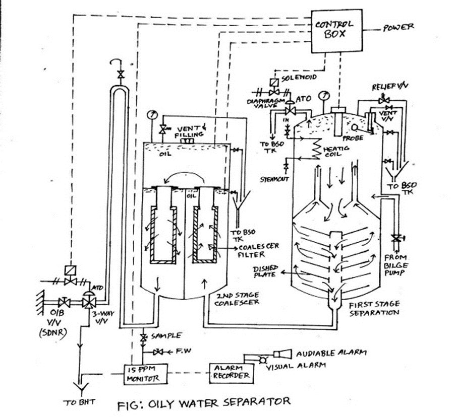
An oily water separator clears the bilge water of oily content to bring it inside the acceptable range to discharge it overboard. An oily water separator is machinery for such importance that it is handled by only the 2nd or chief engineer. (However, the duty engineer might also be asked to operate under supervision)
Operating an Oily Water Separator
An oily water separator can only be operated when the ship is sailing and en route. According to MARPOL, the oil content of the effluent must be less than 15 ppm and the ship has in operation an oil discharge monitoring and control system and oily water separating/filtering equipment.
In case of failure to follow any of the above-mentioned rules, the ship will be fined and stopped, and the chief or 2nd engineer can even be imprisoned.
Operating Procedure
The following points are to be followed while operating OWS.
OWS overboard manual discharge valve is to be kept locked and keys are to be kept with the chief engineer. Open the lock and overboard valve. Open all the other valves of the system.
Open the bilge holding tank valve from which the oily water mixture is to be discharged from OWS.
Open the heater valve.
Open air if the control valves are air operated.
Switch on the power supply of the control panel and OCM unit.
Fill the separator and filter unit with fresh or sea water to clean up and prime the system till the water comes out from vent of second stage.
Start the OWS supply pump which is a laminar flow pump and one that will supply the oily water mixture to OWS.
Observe the OCM for ppm value and keep checking sounding of bilge tank from where OWS is taking suction.
A skin valve/sample valve is provided just before overboard valve and after the 3way valve. Keep a check on the sample for any effluent and clarity.
Keep a watch on the ship side at the overboard discharge valve.
After the operation, Switch off the power and shut and lock the overboard valve. Keys to be handed over to the chief engineer.
Entry to be made by chief engineer in the Oil Record Book (ORB) with signature of operating engineer, chief engineer and the master.
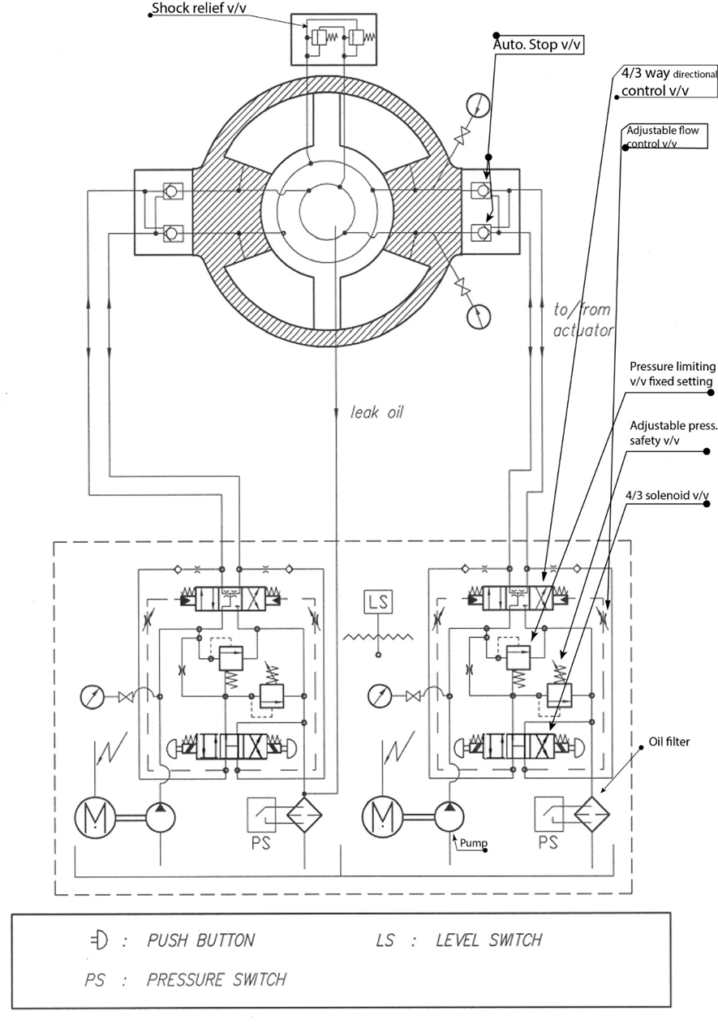
The rotary vane unit is normally fitted with three fixed and three moving vane, and permit a total rudder angle of 70° i.e. 35° in each direction. If larger rudder angle movement is required then only two fixed and two moving vanes will be used, which will permit an angular movement of the rudder of 130°. However the force on the vanes will have to be increased for the same torque as given by 3 vanes.
Steering Methods:
Follow Up” Steering
This is the normal method of steering and involves the feedback of steering angle to the helm. This is suited to both manual and automatic operation. The ships heading may be set into the autopilot which can then compare the actual to desired heading and adjust the rudder angle to suit
Normally used for back up purposes only. Consists of a single lever per steering gear unit, by moving the lever in on direction the rudder will begin to turn, the rudder will continue to turn until the lever is released or it reaches the limit of its operation.
Remote control operation may fail to work and their can be a sudden loss of steering control from the bridge.
This can be due to sudden power failure, any electrical fault in the system or the control system which includes faulty tele-motor which is used for transferring the signal from bridge to the steering unit.
To have control the steering of the ship at such emergency with manual measure from within the steering gear room, an emergency steering system is used.
Action in case of Steering Gear Failure:
If on Auto-Steering, the first action is to change over to manual.
Speed to slow down, proper communication
The 1st suspect is ‘Telemotor failure’.
Switch over to other Telemotor ‘System’ (Marked as System 1 / 2).
If that still does not solve the problem, the next suspect is the Steering Motor.
Change from Steering Motor 1 to Steering Motor 2.
If that still does not solve the problem, next suspect is failure of both telemotor system.
Turn the mode selection switch to NFU (non-follow up steering)
Even if this does not work, it means that all means from steering from the bridge have failed and the last resort of Emergency steering from the Steering gear compartment has to be resorted to.
After each corrective step, the rudder would have to be tried out. Before doing it, pay heed to traffic around to avoid any Closed Quarter’ situation.
If in restricted waters with traffic around, if steering is not restored immediately, Inform ships around through safety message
The procedure and diagram for operating emergency steering should be displayed in steering gear room and bridge.
A hydraulic motor is given a supply from the emergency generator directly through emergency switch board (SOLAS regulation). It should also be displayed in the steering room.
Ensure a clear communication for emergency operation via VHF or ships telephone system.
Normally a switch is given in the power supply panel of steering gear for tele motor; switch off the supply from the panel.
Change the mode of operation by selecting the switch for the motor which is supplied emergency power.
Steering gear with push pin
Steering gear with helm wheel
There is a safety pin at the manual operation helms wheel so that during normal operation the manual operation always remains in cut-off mode. Remove that pin.
Emergency steering gear system is operated by (solenoid button) whether port or starboard
An emergency steering drill should be carried out every month (prescribed duration – 3 months) in the steering gear room with proper communication with bridge to train all the ship’s staff for proper operation of the system so that in emergency situation ships control can be regained as soon as possible, avoiding collision or grounding.
– Sluggish is an operation where the system moves more slowly than usual. This is a sign of reduced performance and functionality. A loss of speed in the system can be caused by low flow rate and one cause could be due to
Steering gear regulations emphasize redundancy to ensure ships maintain steering capability even during system failures. The key redundancy requirements include:
## Main and Auxiliary Steering Gear
Every ship must be equipped with both main and auxiliary steering gear systems. These systems must be arranged so that the failure of one does not render the other inoperative[3].
## Power Units and Control Systems
### Main Steering Gear
For passenger ships, the main steering gear must be capable of operating the rudder as required even with one power unit out of operation. In cargo ships, the main steering gear must be able to operate the rudder as required while all power units are functioning [3].
### Auxiliary Steering Gear
An auxiliary steering gear is not required if the main steering gear comprises two or more identical power units, provided certain conditions are met[3].
## Control Systems
Two independent control systems must be provided for the main steering gear, both operable from the navigation bridge. In tankers, chemical tankers, or gas carriers of 10,000 gross tonnage and upwards, a second independent control system is required even if the primary system is a hydraulic telemotor[3].
## Power Supply
Steering gear control systems operable from the navigation bridge must have their own separate power supply circuits. For ships with rudder stocks over 230 mm in diameter, an alternative power supply must be provided automatically within 45 seconds[3].
## Special Requirements for Large Ships
### Tankers, Chemical Tankers, and Gas Carriers (10,000 GT and above)
The main steering gear must comprise two or more identical power units. The system must be arranged so that steering capability can be maintained or quickly regained in the event of a single failure in any part of one power actuating system[3].
### Ships of 70,000 GT and above
These vessels must also have main steering gear comprising two or more identical power units[3].
## Failure Isolation and Recovery
Systems must be designed to isolate defects quickly and maintain or regain steering capability after a single failure. For hydraulic systems, loss of hydraulic fluid from one system should be detectable, and the defective system must be automatically isolated to keep other systems operational[3].
These redundancy requirements ensure that ships maintain steering capability even in the event of system failures, enhancing overall safety and maneuverability.
SOLAS Chapter II-1 in Part C states steering gear regulation on board a ship.
Regulation 29:
every ship shall be provided with a main steering gear and an auxiliary steering gear. The main steering gear and the auxiliary steering gear shall be so arranged that the failure of one of them will not render the other one inoperative.
Where main steering gear provided with two or more identical power units, an auxiliary steering gear shall not be fitted
Main steering and rudder stock shall be of
adequate strength and capable to steer the ship at max speed
Capable to turn rudder from 35° to 35° either side, from 35° to 30° in not more than 28 sec at deepest draught at max speed
Aux steering able to put from 15° to 15° on either side not more than 60 sec at deepest draught and at ½ speed
Steering gear compartment shall be readily accessible, separate from machinery space, provided with rails and non-slip surface in case of leakage
Rudder stroke diameter minimum 230mm
All components to be of reliable construction
Design pressure for piping and construction at least 1.25x max working pressure
Setting of relief valve not more than design pressure
Steering gear control is provided on both bridge and steering compartment.
Have means provided in steering gear compartment to disconnect control system of bridge
Rudder angle indication independent of control system, indicated on bridge and steering gear
Means of communication provided between bridge and steering gear compartment
Means of indicating power unit if running is installed at ECR and bridge
Low level alarm at each fluid reservoir to ECR, bridge
A fixed storage tank with level indicator having sufficient capacity to recharge at least one power actuating system including the reservoir. The storage tank shall be permanently connected by piping so that the hydraulic systems can be readily recharged.
one of the 2 steering gears should be supplied by the emergency supply. Not only the steering power but also provide power to its associated control system and the rudder angle indicator.
alternate power supply provided in 45sec, supply at least of 30 minute continuous for 10,000 GT, else 10 minute below 10,000 GT
Main and aux steering gear arrange to
a. restart automatically after power failure b. capable of being brought into operation from a position from navigation bridge c. in the event of power failure an audible and visual alarm shall be given. d. In cargo and passenger ship capable of operating rudder with either of the power unit e. Single failure in piping system or any of the power units can be automatically detected, isolated and steering capability automatically regained.
Short circuit protection for steering gear control supply circuit
The electrical power circuits and the steering gear control systems, cables and pipes shall be separated as far as is practicable throughout their length.
Rudder stock 0.23m diameter,
Every tanker, 10,000 GT above and other ships of 70,000 GT, main steering should have 2 identical unit, single failure, steering regained in 45sec.
Interconnection of hydraulic power system provided, loss of hydraulic fluid capable of detection and defective system isolated
Within 12 hours before departure, checking of steering gear system, and communication
Every ship must have both main and auxiliary steering gear.
They must be independent to prevent total failure.
Exception: If main steering has two or more identical power units, auxiliary steering is not required.
Performance Requirements
Main Steering Gear:
Must turn rudder 35° to 35° in ≤28 seconds at max speed and deepest draught.
Auxiliary Steering Gear:
Must turn rudder 15° to 15° in ≤60 seconds at half speed and deepest draught.
Design and Construction
Steering gear compartment: Accessible, separate from machinery space, with safety features.
Minimum rudder stock diameter: 230mm.
Components must be reliable.
Piping design pressure: ≥1.25x max working pressure.
Relief valve setting: ≤design pressure.
Control and Communication
Control on bridge and in steering compartment.
Bridge control can be disconnected in steering compartment.
Independent rudder angle indicators on bridge and in steering compartment.
Communication between bridge and steering compartment required.
Power unit status indicators in ECR and on bridge.
Safety and Emergency Features
Low fluid level alarms to ECR and bridge.
Fixed storage tank for hydraulic system recharge.
Emergency power supply for one steering gear.
Alternate power supply within 45 seconds.
Automatic restart after power failure.
Audible and visual alarms for power failures.
Automatic fault detection and isolation.
Short circuit protection for control circuits.
Special Requirements for Large Ships
Tankers ≥10,000 GT and other ships ≥70,000 GT: Main steering with two identical units, 45-second recovery.
Maintenance and Testing
Pre-departure checks within 12 hours.
Emergency steering tests every 3 months.
Remember the key numbers: 35°-30° in 28 seconds for main, 15°-15° in 60 seconds for auxiliary, 230mm minimum rudder stock diameter, and 45-second recovery time for large ships.
Scale formation in freshwater generator can be controlled and minimized by continuous chemical treatment.
Poly-sulphate compounds (like sodium poly-sulphate) with anti-foam is preferred by marine engineers and is extensively used on ships. Their trade name is different, like:
Vaptreat (by “UNITOR”)
Ameroyal (by “DREW CHEMICALS”)
These chemicals minimize calcium carbonate scale formation and possibility of foaming. the compound is nontoxic, no-acidic, and can be used in fresh water generator producing water for drinking purposes.
Boiler water test
.bwt .boiler water
Alkalinity test/ pH value:
(9.5~10.5) Sodium hydroxide is usually added to maintain alkaline condition. (200-700ppm)
Chloride level:
Regular testing of chloride ensures the monitoring of any seawater contamination and any leak from aux condenser. (60-200ppm)
Phosphate level:
Sodium phosphate acts as water softener. They precipitate the scale forming compounds specially calcium sulphate from the boiler water to prevent scale deposit (30-50 ppm)
Conductivity/ hardness test:
Measured in micro siemens per cm. The reading determines the hardness of the water which is the TOTAL DISSOLVED SOLID (TDS)
Hydrazine level:
Correct dosage prevents oxygen formation. Max 50 ppm
N2H4+O2=2h2O+N2
Present chemicals used:
Oxygen inhibitor
Oxygen Control
Oxygen scavenger
Standard Value for Boiler Water
Engine Cooling water Test:
pH value:
pH value should be kept at 7-8 at 25° C.
test cooling water every after 240 hours, add chemicals if pH value falls below 7.
If pH value goes over 10 , some amount of cooling water need to replaced.
Maintain pH value in alkaline range to prevent corrosive environment.
Nitrite (Anti-corrosive element):
Nitrite is used as an inhibitor to prevent corrosion in cooling systems. It promotes the formation of protective films on surfaces and inhibits corrosion by preventing oxygen-related corrosion. Nitrite levels should be checked frequently and treated with chemicals if levels are low. A common range for nitrite concentration is 500 to 1,500 ppm.
Keep nitrite value above 1500ppm.
Chloride content increasing:
→ Check possibility of seawater penetrating into cooling water.
→ Check the system which includes sea water, for example fresh water cooler cooled by sea water.
pH value decreasing or sulphate content increasing:
→ Check if cooling water is contaminated by exhaust gas.
Cooling water temp high, less flow of cooling water due to choked valve, pipe leakage, if SW cooled—may be SW O/B valve choked.
Wrong grade, Poor quality oil.
Insufficient LO, oil leakage, seal broken, sump level may low.
LO Contaminated with Bearing / foreign particles – Replenish the oil.
Failure of LO supply mechanism.
Ambient temp high.
Misalignment of the shaft due to Shaft & Hull distortion or Internal bearing wear down.
Shaft got misaligned due to bearing wear down (rare to happen, can be detected by taking crankshaft deflection after engine is stopped).
Others bearing wear down.
Deformation of tank top due to excessive heating of DB tk ( Bilge tk, Sludge tk).
Excessive vibration of shaft due to propeller damage.
Excessive vibration, ME running on critical speed for a long time – Avoid running in critical speed.
Hogging & Sagging effect.
If ship listed – correct list.
And also check trim condition – correct trim.
As a Chief Engr Actions :
Check temperature locally and manually by temp gun.
Check the level, appearance of oil and cooling line.
Inform Master, Bridge if problem is real & Reduce RPM.
I will instruct to 3/E to Start another A/E & keep eye on Boiler steam pressure.
Engine should slow down automatically, if not, need to be slow down manually until it cool down.
Check Causes for running Hot & take necessary action.
I will instruct to 4/E engineer to check cooling water supply and arrange extra cooling means.
I will tell 2/E to renew oil by flushing with new oil, Check drain oil quality.
If ship is listed, inform Bridge to correct the list.
In extreme case, Ask bridge to stop engine if possible.
If not possible to stop engine, continue with minimum possible rpm and strictly monitor the temp of int. bearing and other parameters as well specially the crankcase condition (as misaligned shaft may damage main bearings and can lead to crankcase explosion).
In the meantime, investigate the cause of this high temp. if possible do troubleshoot.
When it is port, re-metal bearing & adjust chocks to give correct share of load. If overheating is frequent, check shaft alignment (Methods : Optical Sighting, Piano Wire, Gap & Sag Method, Jack-up Method, Strain Gauge Method), Check holding down bolt.
Check main engine crankshaft deflection and bearing clearances
Verify onboard LO analysis records
Execution Phase
Safety Measures
Conduct risk assessment before starting work
Hold toolbox meeting with dock supervisor and service team
Initial Inspections
Turn shaft to zero marking and check clearance
Isolate and drain the system
Measure propeller drop/stern tube wear down clearance using poker gauge
Compare readings with previous records and maker’s limits
Chrome Liner Inspection
Check for:
Wear down
Scoring marks
Cracks
Seal Replacement
Decide whether to change seal in-situ or remove propeller
If propeller is removed, inspect stern tube bearing for:
Lacquer formation
Signs of overheating
Fretting marks
Metal peeling
Reassembly and Testing
Pay attention to alignment of stern tube and propeller shaft
Replenish lubricating oil and conduct leak test
Recheck poker gauge reading at ZERO mark with all main engine units in place
Key Points to Remember
Perform leak test after flushing pipes
Take wear-down readings before and after overhauling AFT seal
Protect seals from external damage (sandblasting, painting, welding, chemicals, heat)
Use stainless steel fitting bolts (SUS 316 or equivalent) for AFT seal installation
Secure all fitting bolts and plugs with stainless steel wire
Return all valves to “Normal Operating Condition” after testing
Monitor oil level for sudden reduction due to air-locking dissolution
Explain the procedures of stern tube alignment checks in dry dock
.stern tube alignment .st alignment
• Dial gauge for radial direction:
o This gauge is set up to measure the radial movement of the shaft. Radial direction reefers to a direction that radiating out from the center of the shaft
o It is important to measure this to ensure that the shaft is perfectly centered & there is no excessive play or wobble which would indicate misalignment
• Dial gauge for radial direction (On another point):
o This second dial gauge is measuring the radial displacement likely at different point along the shaft to measure consistency in shaft alignment throughout its length
• Dial gauge for axial direction:
o the axial direction is along the length of the shaft. This gauge measures the end play or axial movement of the shaft. It is crucial to measure that the shaft doesn’t move too much back and forward along its length, which could affect in the operation of the seal and further lead to leak or wear
In a stern tube seal alignment check gauges would be used as follows:
• The dial gauges are positioned at a specific point on the stern tube and propeller shaft
• The shaft then to be rotated and the reading to be observed at the dial gauge
• By reading the gauges we can determine if there is any misalignment in the shaft. This is determined by looking for variations in the variations of the reading which would indicate that the shaft is not perfectly round or is not seated centrally within the stern tube.
• Any misalignment can lead to excessive wear in the seal & bearing and potentially lead to seal failure
• Therefore, it is crucial to adjust the alignment until the reading on the dial gauges are within acceptable limits as specified by the manufacturer.
Measuring item
Position
Size 670 & below
Size 710 & above
Eccentrically
A, B
0.2 mm
0.3 mm
Squareness
C
0.1 mm
0.15 mm
Clearence
D, E
0.5 mm
0.7 mm
Note: In case adjusting liner eccentrically by turning shaft isn’t available, then even clearance between liner bore and shaft surface by using feeler gauge must be achieved.
Causes & Actions in case of Sea Water Ingress in Stern Tube
.stern tube water ingress
Causes:
Seal Ring damage.
Scored Chrome Liner
Seal Assembly loose & crack.
Oil line or air line leaking in aft peak tk
Fishing net caught in the Aft Seal assembly.
Bearing wear down will allow the shaft to drop, causing the seal to overload, clearance may develop between seal & liner.
Low LO pressure or air pressure
Misalignment & vibration
LO cooler sw side leaky.
Actions @ SEA:
Reduce engine RPM
Reduce Aft draft is possible
Check sea water cooled LO Cooler.
Increase oil pressure/air pressure in seal by raising height of gravity tk or adjust air pressure or increasing tk back pressure or using high viscous oil (Gear oil, mixing grease).
Actions @ Port:
Check seal, if damage renew.
If fishing net, removed by driver.
If Chrome plate liner scored, machined it (Dia must be within limit) / Shift seal position by changing the distance piece position.
how oil loss due to seal failure can be restricted while on passage
Under normal condition, seal activated through #3 sealing ring.
(valve V3 & V4 normally open).
If oil leakages take place, shut V3 & V4 respectively and drain line – #3S will be activated.
Pipeline connection to oil tank for chambers #2 & #3 seal – prevent oil loss into the sea.
Sea water ingress into stern tube by draining into collection tank. If #3 & #3S sealing rings are both damaged, stern tube hydrostatic oil pressure to be lowered – using temporary oil tank & vinyl hose.
Sealing arrangement
(A) Sealing arrangement
The SEAL is composed of an AFT SEAL, which prevents stern tube lubricant oil leakage outside the ship as
well as seawater from entering the stern tube, and a FORWARD SEAL which prevents stern tube lubricant oil
leakage into the engine room.
Aft Seal: The Aft Seal can be broadly divided into the casing, which is fixed to the hull, and the chrome steel
liner, which is fixed to the propeller boss and rotates with the propeller shaft.
The casing is composed of three kinds of metal rings; flange ring, intermediate ring and Cover ring, which are
tightened to each other with bolts. Three or four sealing rings are assembled between the metal rings with
their pointed ends (lip section) touching the chrome steel liner. The lips are pressed hard against the rotating
liner and maintain a sealing effect through water pressure, oil pressure, the elasticity of the sealing ring and
the tightening force of the springs.
The sealing rings are numbered 1, 2 and 3 in order from the seawater side. The No.1 and No.2 sealing rings
close out seawater, while the No. 1 sealing ring also has the function of protecting the inside of the stern tube
from foreign matter in the seawater. Lubricant oil in the stern tube is sealed with the No.3 sealing ring.
Itemise the factors which adversely affect seal life.
Rubber seal harden/deteriorate
Damaged due to foreign objects-rope, fishing nets, sand
Distortion/rupture of seals due to high pressure differential
Air Sealing:
Sealing arrangements:
.stern tube
→System operates by spouting air into the sea.
→Leakage of system by sea water or oil in system is drain down to a collection tank (leakage tank)
→Air pressure passing through #2/3 seal is about 0.2~0.4 bar higher than sea water
→The S/T LO tank is set about 2~3 meters above the propeller shaft centre line. This tank is air tight and connected to air control unit. The air pressure in the tank is same as air pressure through #2/3 chamber.
→LO pump when running passes through #3/3S seal. A needle valve in system is to be adjusted to adjust the LO pressure to about 0.3~0.5 bar higher than air pressure in #2/3 chamber.
Oil filling:
→Close air supply
→release air pressure
→meantime sea water pressure on seal no-01 will prevent water from entering to engine room
→ fill required amount of oil and afterwards normalize the system
→ Optional ceramic coating if applied on running surface, heavy duty rings are mandatory
Chrome liner fitting:
Seal is gripping on to the chrome liner. Chrome liner is bolted on to propeller boss(aft). An o’ring is fitted between the chrome liner and propeller boss to prevent sea water ingress.
Fwd chrome liner is fitted on to a clamp ring . Clamp rings are of 2 halves and have holes.
Aft sealing assembly consist of 2 main and 1 aux sealing rings. All sealing rings are spring loaded . Fwd sealing ring prevent oil leakage to sea .Lip seals hold oil within Stern tube and accepts small misalignment
O ring fitted between boss and liner
Chrome liner act as rubbing surfaces for lip seals. The chrome liner at the aft end protects the steel shaft from seawater and corrosion .Grooving will not happen on the shaft because of liner, so that the chrome liner can be machined or can be shifted axially by putting spacer. If grooving occurs leak will start.
Seal no#2 and no#3 is connected to air supply system ,#3s is the spare seal
If water content found on the stern tube that means along with #1 and #2 , then #3 seal is also leaking. Then we have to put #3s seal in use.
Causes & Actions in case of seal failure?
Causes:
Seal Ring damage.
Scored Chrome Liner
Seal Assembly loose & crack.
Oil line or airline leaking in aft peak tank
Fishing net caught in the Aft Seal assembly.
Bearing wear down will allow the shaft to drop, causing the seal to overload, clearance may develop between seal & liner.
Low LO pressure or air pressure
Misalignment & vibration
LO cooler SW side leaky
Action:
AT SEA:
Inform master
Reduce engine RPM
Reduce Aft draft is possible
Check sea water cooled LO Cooler (If SW ingress)
Increase oil pressure/air pressure in seal by raising height of gravity tank or adjust air pressure or
increasing tank back pressure or using high viscous oil (Gear oil, mixing grease)
Isolate LO between #3 & #3S seal and activate #3S only
If SW ingress found in drain collection tank, then water is coming due to failure of #1 or #2 seal ring, in that case AIR PRESSURE need to be adjusted higher than SW pressure
o AT PORT:
Inform office
Arrange for a diving team for inspection
If rope guard is damaged or propeller shaft entangled with fishing net then those
needs to be removed
Eventually replacing seal in-situ by shore team if possible
Measures to be taken before propeller is fitted back:
Ensure M/E is not turned.
Test report of seal assembly to be checked.
Report of tail shaft cone polishing and crack test to be checked.
If propeller is repaired, then repair report.
Propeller polishing and crack test report.
Visual inspection of threaded part of shaft and pilgrim nut.
Radial reference mark on both propeller and shaft to coincide
Final push up pressure according to the manufacturer’s instruction.
Loading ring should not come out more then 1/3rd of the ring width.
Distance travelled by the propeller boss.
Nut and bolt to be wire lashed.
When fixing ensure maker instruction to be followed.
Construction diagram of controllable pitch propeller:
A controllable pitch propeller is made up of a boss with separate blades mounted into it. An internal mechanism enables the blades to be moved simultaneously through an arc to change the pitch angle and therefore the pitch. A typical arrangement is shown in Figure below.
When a pitch demand signal is received a spool valve is operated which controls the supply of low-pressure oil to the auxiliary servo motor. The auxiliary servo motor moves the sliding thrust block assembly to position the valve rod which extends into the propeller hub. The valve rod admits high-pressure oil into one side or the other of the main servo motor cylinder. The cylinder movement is transferred by a crank pin and ring to the propeller blades.
The propeller blades all rotate together until the feedback signal balances the demand signal and the low-pressure oil to the auxiliary servo motor is cut off.
To enable emergency control of propeller pitch in the event of loss of power the spool valves can be operated by hand.
With the hydraulic mounting method using pilgrim nut, keyless propeller is now a standard feature in propeller mounting on fixed pitch propeller on cargo ships.
Final push up pressure and travel distance according to instruction manual.
Loading ring should not come out 1/3 of the ring width.
Uniform stress distribution.
Boss made of bronze, shaft made of alloy steel.
Keyless fitting relies on the good interference fit between the propeller boss and the taper end of tail shaft
This method removes problems associated with keyways and facilitates propeller mounting and removal using hydraulic nut.
The reliability of keyless propeller depends on the accuracy of the hub and shaft tapers and correct grip from the stretched propeller hub on the shaft.
The degree of stretch (or strain) is controlled by the amount of push up. It must ensure adequate grip despite temperature changes and consequent differential expansion of bronze hub and steel shaft. It must also avoid over stressing of the hub and in particular any permanent deformation.
Lloyds require that the degree of interference be such that the frictional force at the interface can transmit 2.7 times the nominal torque when the ambient temperature is 35°C.
Lloyds also require that at 0°C the stress at the propeller bore shall not exceed 60% of the normal stress.
Initially, MV=SV, PV1=C.SP1, PV2=CSP2, a ≈ b, c ≈ d. If steam demand ↑, MV↓ O/P of R/A Master Controller ↑, c↑ , a↑ c > d, d passes through LSS, so no change in CSP1, But a > b, ‘a’ passes through HSS, CSP2↑, PV2↓ wrt CSP2 O/P of D/A Air flow controller ↓ ATC air damper opens more, Combustion Air flow ↑, d↑, d passes through LSS since d < c, CSP1 ↑, PV1↓ wrt CSP1, O/P of R/A Oil flow Controller ↑, ATO oil control valve opens more, Steam pressure restored to SV within a few cycles due to I-action of the Master controller. The control scheme above ensures that air is increased ahead of fuel to prevent fuel-rich condition when load ↑. And similarly, fuel will be decreased ahead of air to prevent fuel-rich condition when load ↓
DP cell
Purpose and Overview
The boiler DP cell is used for remote indication of boiler water level, which is crucial for safe and efficient boiler operation.
Key Components
Main parts of the system:
Boiler Drum: Contains water and steam under pressure
DP Cell: Measures differential pressure between two points
Equalizing Leg: Minimizes damping action and stabilizes measurements
Valves: Used for system isolation and maintenance (NO and NC)
Operating Principle
DP cell working:
It measures the pressure difference between the low pressure (LP) and high pressure (HP) sides of the boiler
LP side connects to the bottom of the drum, measuring water column pressure
HP side connects to the top, measuring water column plus steam pressure.
Key Equations
LP = ρg(H1 + H2)
HP = ρg(H1 + H2 + H3)
ΔP = HP – LP = ρgH3
Where ρ is water density, g is gravitational acceleration, and H3 is the water column height above the lower tap.
Interpretation and Calibration
ΔP is proportional to H3, indicating water level above the lower tap
As water level (H2) decreases, H3 and ΔP increase
The system is calibrated with 20 PSI for low level and 3-15 PSI for the operating range.
Practical Implications
Important for remote monitoring
It contributes to boiler safety and efficiency
Water level changes according to DP cell output.
Air to close:
Air to close valves is normally held opened by the spring and require air pressure (a control signal) to close them – they close progressively as the air pressure increases.
Why ATC?
To provide failsafe arrangement.
Example:
Jacket water temperature controller. During failure air will shut, bypass valve open, controller will direct water to cooler. Excessive cooling may occur, but this is safe for engine.
Air to open valve:
Opening valves is normally held closed by the spring and require air pressure (a control signal) to open them – they open progressively as the air pressure increases.
Why ATO?
It is decided according to fail safe arrangement.
Example: A fuel supply valve, any failure of power or air supply will cause the valve to close by spring pressure.
Capacitance type level sensor:
.level sensor .capacitance type level sensor
Principle
A capacitive probe is placed inside the content of the tank where level is to be measured. This method is based on the fact that the capacitance between a stationary probe and the vessel wall depends on the liquid level around the probe and the fluid dielectric constant.
Principal Features
An insulated rod is inserted into the tank. Normally, a metal rod coated with PVC or PTFE is used to prevent corrosion.
The capacitance between the rod and the tank walls has two components: C1 above the liquid (or solid) surface and C2 below. These capacitances depend on the geometry of the installation (for example. rod diameter and the distance to the wall) and the dielectric constants of the liquid and the vapour above the surface. The basic capacitor equation is:
Here, C=capacitance
As the liquid level rises, C1 will decrease and C2 will increase in value. The two capacitors are effectively in parallel, and as liquids and solids have a higher dielectric constant than vapours, the net result is an increase in capacitance with level.
The change in capacitance is small that abridge/amplifier circuit is used.
A whitstone bridge is used to sense the change in level. The whitstone bridge stays at a balanced position, no current flows through its output terminals. When the capacitance changes due to the rise of liquid whitstone bridge will become unbalanced and its output terminal will conduct electricity. This output signal is then used as a process value.
The main benefit of capacitance probes is that it works with a wide range of liquids and solids.
These type of level sensor have to be designed specifically for each and every application with regard to tank geometry and dielectric constant of the liquid present in the tank.
Viscosity Regulator or Viscotherm, is a device used to measure viscosity of the fuel oil before sending it to the engine. It is generally fitted at the outlet of the fuel oil heater. The regulator is connected with the heater so that it can measure the viscosity of the oil and regulate the temperature at the same time.
Viscosity regulator is an “L” shaped instrument which consists of a small gear pump that rotates at a constant slow speed of 40 rpm. The pump takes suction from the heater discharge and is generally fitted close to it. A regulated flow of fuel is sent by the pump to a capillary tube. The capillary tube is so designed that the form of flow between the inlet and outlet of the tube generates a pressure difference, which is equal to the viscosity of oil flowing through it. the flow through the capillary is laminar, the difference in pressure between each end of the tube is directly proportional to the viscosity of the oil (the higher the viscosity, the higher the pressure differential).
A positioner is a motion-control device which actively compare stem position against the control signal, adjusting pressure to the actuator diaphragm or piston until the correct stem position is reached.
Relationship between the v/v steam movement and actuating pressure will be linear only if there are two forces acting against each other, one is downward air pressure to actuator and other one is upward spring force.
Unfortunately, there exist many other forces acting on a valve stem besides the actuator force and the spring’s reaction force. Friction from the stem packing is one such force, and reaction force at the valve plug caused by differential pressure across the plug’s area is another. These forces conspire to re-position the valve stem so stem travel does not precisely correlate to actuating fluid pressure.
Due to these other forces relationship is not linear. A common solution to this dilemma is to add a positioner to the control valve assembly.
Positioners essentially act as control systems within themselves: the valve’s stem position is the process variable (PV), the command signal to the positioner is the setpoint (SP), and the positioner’s signal to the valve actuator is the manipulated variable (MV) or output. Thus, when a process controller sends a command signal to a valve equipped with a positioner, the positioner receives that command signal and applies as much or as little air pressure to the actuator as needed in order to achieve that desired stem position. Thus, the positioner will “fight” against any other forces acting on the valve stem to achieve crisp and accurate stem positioning according to the command signal. A properly functioning positioner ensures the control valve will be “well-behaved” and obedient to the command signal.
Boiler level controller (2 element):
Initially the 2-element control system is operating under normal load condition and MV = SP, PV = CSP and LCV= 50% open.
If large & sudden↑ in steam load arises, the 2-element control system will respond as follows:
FT senses rise in steam flow
PV ↑
O/P (output) of R-A slave controller↓
ATC LCV opens more increasing feed water supply
In the meantime, steam pr ↓ and ACC increase fuel to burner and water level ‘Swell’ in steam drum
MV↑
O/P of D-A Master controller↑
CSP of Slave controller↑
PV ↓ w.r.t. CSP↑
O/P of R-A Slave controller↑
ATC LCV closes towards 50%
The two-element control system provides better control than single-element system because the LCV was opened more than 50% and then closes back towards 50% resulting in a net increase in feed water supply. Thus a dangerous drop in water level is avoided, as shown in ‘green’ making it suitable to deal with large and sudden increase in load.
Two element boiler level controller:
Explanation → start from slave controller
Boiler demand increase→ flow reduce → goes to slave controller (start like this)
PV and P bellows same side means→ negative feedback
The square root extractor is an electronic (or pneumatic) device that takes the square root of the signal from the flow transmitter and outputs a corresponding linear flow signal.
Purpose of its use
The square root extractor is used to convert the measured differential pressure into flow rate. signal is found to vary as the square of the measured flow rate, Q, based on eqn (*) and the basic flow rate equation Q = A (flow area) x V (velocity) That is, Q2 α ∆P, where Q α √∆P. Hence, a square root extractor is required on the ∆P signal in order to measure Q.
Why it is not used in level/temperature transmitter.
Because the relationship between the variables are linear so no need of an square root extractor.
oil tankers of 150 gross tonnage and above shall be provided with effective oil/water interface detectors approved by the Administration for a rapid and accurate determination of the oil/water interface in slop tanks and shall be available for use in other tanks
Control
.fail safe
P action:
Proportional action is the when the controller output signal is proportional to the deviation of the measured value from the set value. Alternatively, the rate of change of output signal is proportional to the rate of change of deviation.
Proportional band:
The proportional band is defined as the amount of change in input (or deviation), as a percent of span, required to cause the control output to change from 0% to 100%
Proportional Gain is the ratio of output change (%) over the measured variable change (%) that caused it.
If proportional band is 25% then the proportional gain is 4.
I action:
Integral action time: The time a integral controller take to produce the same output as a P controller.
D action:
The rate of change of input(deviation) is proportional to controller output.
It has a stabilizing effect but can not be used alone.
The derivative or differential controller is never used alone. With sudden changes in the system the derivative controller will compensate the output fast. The long term effects the controller allow huge steady state errors.
Fail safe in a pneumatic control systems ?
On failure of control air supply, the pneumatic actuator may be arranged to move to a position that allows the plant to continue to operate safely, in other words, fully opened or fully closed. This is known as fail safe. For example, in the case of a jacket cooling water system, on failure of control air, the actuator opens fully to allow jacket water to the cooler without bypass. On the other hand a fuel oil control valve for boiler closes completely on such a failure. This ensures safety of the plant.
Fail-Safe condition:
In boiler auto combustion control system,
“Fail-safe” conditions are ensured by shutting off fuel oil to burners under certain fault conditions relating to loss of power supplies arising in the ACC.
They are ensured as follows:
1. Loss of ACC electric power supply: A sol- operated 3- way v/v de-energizes & vents the actuator air from FO control v/v.
2. Loss of actuator power to FO Control v/v:
ATO type FO control v/v shuts automatically.
3. Loss of Level Transmitter power (pneumatic or electric): A solenoid operated 3-way v/v de-energizes & vents the actuator air from FO control v/v.
Case 1: Pneumatic Level Transmitter
Case 2: Electronic Level transmitter
Fail set
.fail set
In some other systems, control air supply failure locks the position of valve at that time of failure. This is called fail set. The advantage of this system is that the plant gets stable and have time for normal shutdown or can wait for reestablishment of control air supply for some time. Example for such a system is boiler water level control.
Hysteresis
.hysteresis
The difference between up scale and down scale results in instrument response when subjected to the same input but approached from the opposite direction
Example: A control valve has a stroke of 1.0 inch and we give the valve a 9 psig signal. The valve trave0ls 0.500 of an inch. We then give the valve a 12 psig signal, and the valve travels to 0.750 an inch. When the valve is then given a 9 psig signal, the stroke is measured at 0.501. That represents hysteresis.
Hysteresis can be caused by packing friction, loose linkage, pressure drop, etc.