Desirable Properties of Marine Refrigerants

Desirable Properties of Marine Refrigerants

When selecting refrigerants for shipboard use, the following properties are considered ideal:

  • Low Specific Volume: Reduces the size requirements for compressors and piping.
  • High Critical Temperature: Allows condensation at higher temperatures, which is beneficial in varying marine climate.
  • High Latent Heat of Vaporization: Ensures efficient heat absorption during the evaporation process.
  • Chemical Stability: Resists decomposition under operating conditions.
  • Environmental Friendliness: Low ODP and GWP values are preferred to minimize ecological impact.
  • Non-Corrosive: Prevents damage to system components.
  • Non-Flammable and Non-Explosive: Enhances safety aboard ships.
  • Compatibility with Lubricants and Materials: Ensures smooth operation and longevity of the system.
  • Easy Leak Detection: Facilitates maintenance and prevents environmental harm.

Key Refrigerant Properties Comparison

Refrigerant ODP GWP Pressure Level Flammability Typical Use
R-134a 0 1,430 Medium Non-flammable Marine AC
R-404A 0 3,922 High Non-flammable Freezers
R-407C 0 1,774 Medium-High Non-flammable AC/Refrigeration
R-410A 0 2,088 Very High Non-flammable High-efficiency AC
-744 (CO2) 0 1 Extremely High Non-flammable Eco-friendly systems

Note: The critical temperature of a substance is the highest temperature at which it can exist as a liquid, regardless of the pressure applied. Above this temperature, the substance cannot be liquefied by pressure alone and will exhibit properties of both gases and liquids.


MPA Singapore Approved Class


MPA approved class

The Maritime and Port Authority of Singapore (MPA) has authorized the following eight classification societies to act as Recognized Organizations (ROs). These societies are empowered to perform statutory surveys, certifications, and audits on behalf of the Singapore flag administration for vessels registered under the Singapore Registry of Ships (SRS).

MPA-Approved Classification Societies:

1.      American Bureau of Shipping (ABS)

2.      Bureau Veritas (BV)

3.      China Classification Society (CCS)

4.      Det Norske Veritas (DNV)

5.      Korean Register of Shipping (KR)

6.      Lloyd’s Register (LR)

7.      Nippon Kaiji Kyokai (ClassNK)

8.    Registro Italiano Navale (RINA)

These classification societies are also designated as Recognized Security Organizations (RSOs), authorized to conduct security assessments and issue International Ship Security Certificates (ISSC) in accordance with the International Ship and Port Facility Security (ISPS) Code.


Certificates and supplements required to carry on board.


What are the certificates and supplements required to carry on board.

MARPOL

1.      International Oil Pollution Prevention Certificate MARPOL Annex I Supplement:

Record of Construction and Equipment for Ships Other Than Oil Tankers (Form A) or Record of Construction and Equipment for Oil Tankers (Form B

2.      International Pollution Prevention Certificate for the Carriage of Noxious Liquid Substances in Bulk (NLS Certificate) MARPOL Annex II

3.      International Sewage Pollution Prevention Certificate MARPOL Annex IV, reg

Supplement:

         Description of sewage treatment plant or holding tank system

         document of approval for the rate of sewage discharge.

4.      Garbage Management Plan MARPOL Annex V, reg 10

5.      International Air Pollution Prevention Certificate MARPOL Annex VI

Supplement:

         Technical details of engines and equipment for NOx, SOx, and particulate matter control

         EIAPP Certificate (Engine-specific NOx certificate) may also accompany

6.        International Energy Efficiency Certificate MARPOL Annex VI,- validity lifetime

Suppliment: seemp

7.        International Ballast Water Management Certificate; BWM convention

         Supplement:

         Ballast Water Management Plan and system details

SOLAS

1.              Passenger ship safety certificate SOLAS 1974, supplement: form P

2.              Special Trade Passenger Ship Safety Certificate

3.              Special Trade Passenger Ship Space Certificate STP 71, rule 5

4.              Cargo Ship Safety Certificate SOLAS 1988, reg I/12 supplement: form C

5.              Cargo Ship Safety Construction Certificate SOLAS 1974, regulation I/12

6.              Cargo Ship Safety Equipment Certificate SOLAS 1974, reg I/12 supplement:

      Form E

      Inventory of life-saving appliances, Radio installations and fire-fighting appliances

7.       Cargo Ship Safety Radio Certificate SOLAS 1974, reg I/12 supplement:

                                              Form R

8.      Document of authorization for the carriage of grain and grain loading manual SOLAS 1974, reg VI/19

9.      Document of compliance for ships carrying dangerous goods SOLAS chap 2 reg 19

Supplement:

                                      Types of dangerous goods permitted and safety measures in place

10.    Document of compliance SOLAS, ISM Code

11.    Safety management certificate SOLAS, ISM Code

12.    International Ship Security Certificate (ISSC) or Interim International Ship Security Certificate SOLAS 1974

Suppliment: SSP

13.    Continuous Synopsis record SOLAS

14.    Minimum safe manning document SOLAS

15.    Voyage data recorder system – certificate of compliance SOLAS 1974, reg 5

Other

1.               International Tonnage Certificate (1969); Tonnage convention – lifetime validity Supplement:

Details of gross and net tonnage calculations

2.               International Load Line Certificate; LL convention Supplement:

      Freeboard assignment details

      Conditions of assignment (closing appliances, machinery space openings, etc.)

2.  International Load Line Exemption Certificate ;LL Convention 4.        International Anti-fouling System Certificate ,AFS Convention

Supplemented: Record of Anti-fouling Systems,

5.       Declaration on antifouling system AFS Convention, reg 5 6.          Certificates for masters, officers or ratings STCW 7. MLC (Maritime Labor Convention) Certificate: supplements:

      DMLC Part-1 (issued by Flag state)

      DMLC Part-2 (issued by Company)

8.      International Certificate of Fitness for the Carriage of Dangerous Chemicals in Bulk IBC code

9.      International Certificate of Fitness for the Carriage of Liquefied Gases in Bulk IGC Code

10.  Certificate of insurance or other financial security in respect of civil liability for oil pollution damage CLC 1969, article VII

11.  Certificate of insurance or other financial security in respect of civil liability for bunker oil pollution damage Bunker convention 2001

12.  Certificate of Registry

13.  Certificate of class

14.  P&I Certificate of Entry

A Supplementary Certificate for a Statutory Certificate is an additional document issued alongside a main statutory certificate to provide specific details or conditions not covered directly in the primary certificate.

 

Anti fouling System Convention


Anti-Fouling Convention


Q. Anti Fouling Convention

The International Convention on the Control of Harmful Anti-Fouling Systems on Ships, commonly called the
Anti-Fouling Convention (AFS Convention), is an IMO treaty aimed at protecting the marine environment from the harmful effects of anti-fouling paints and coatings used on ships’ hulls.

Purpose of the AFS Convention
  • Prohibit the use of harmful anti-fouling paints.
  • Ensure environmentally safe alternatives are used.
  • Prevent contamination of marine ecosystems and protect marine life.
Applies to
  • It applies to all ships of 400 gross tonnage and above engaged in international voyages, excluding fixed or floating platforms, FSUs, and FPSOs constructed before 1 January 2003 and not dry-docked since then.
  • Ships between 24 meters in length and 400 GT must carry a Declaration on Anti-fouling Systems confirming compliance.
📦What Are Anti-Fouling Systems?

Anti-fouling systems are coatings or paints applied to a ship’s hull to prevent the growth of:

  • Barnacles
  • Algae
  • Mollusks
  • Marine organisms

These organisms increase hull resistance, leading to:

  • Higher fuel consumption
  • Reduced speed
  • More emissions

Harmful Substances Banned
  • Tributyltin (TBT): Banned from 1 Jan 2008. Highly toxic to marine life (e.g., causes imposex in snails).
  • Cybutryne (Irgarol 1051): Banned from 1 Jan 2023. Ships must remove or seal it by 60 months after entry into force (by 1 Jan 2028).
Compliant Anti-Fouling Systems

Modern anti-fouling systems include:

  • Biocide-free coatings
  • Silicone-based foul-release coatings
  • Copper oxide (Cu2O)-based (still allowed, though monitored)
  • Electrolytic and ultrasonic systems
📝Certification Requirements
  • International Anti-Fouling System Certificate (IAFSC)
  • Record of Anti-Fouling System

    • Describes type of system used
    • Must include evidence of compliance


Types of bulk carrier

Bulk carrier ships are specialized merchant vessels designed to transport unpackaged bulk cargo such as grain, coal, ore, steel coils, and cement in their cargo holds. They come in various types and sizes, categorized mainly by their deadweight tonnage (DWT), dimensions, and operational design. Here is a detailed overview of the types of bulk carrier ships:

    • Capacity: 1,000 to 10,000 tons

    • Length: 100 to 130 meters

    • Draft: Less than 10 meters

    • Usage: Often used on rivers and for short international distances7.

    • Capacity: 15,000 to 40,000 DWT

    • Features: Can berth and operate in most ports worldwide due to smaller size and shallower draft

    • Usage: Versatile for various cargoes and routes17.

    • Handymax Capacity: 40,000 to 50,000 DWT

    • Supramax Capacity: Up to 60,000 DWT

    • Length: Around 150–200 meters

    • Features: Equipped with cranes for self-loading/unloading; suitable for longer voyages and diverse cargoes

    • Usage: Popular for transporting coal, grain, cement, steel, fertilizer, and more

    • Capacity: 65,000 to 89,999 DWT

    • Dimensions: Designed to fit the old Panama Canal locks

    • Usage: Common for iron ore, grain, and coal transport; can access many global ports

    • Capacity: 80,000 to 200,000 DWT (commonly 130,000 to 170,000 DWT)

    • Length: Approximately 230 to 290 meters

    • Draft: Around 17 to 18 meters

    • Features: Too large for Panama and Suez Canals; must navigate around Cape Horn or Cape of Good Hope

    • Usage: Mainly for coal, ore, and other raw commodities; includes subtypes like Very Large Ore Carriers (VLOC) and Very Large Bulk Carriers (VLBC)

    • Capacity: 180,000 to 400,000 DWT

    • Length: Up to 360 meters

    • Draft: 20 meters or more

    • Usage: Specialized for iron ore transport, especially on routes between Brazil, Europe, and Asia; Valemax is a specific class owned by Vale mining company

    • Capacity: Up to 400,000 DWT

    • Length: About 360 meters

    • Width: 65 meters

    • Draft: 25 meters

    • Usage: Largest bulk carriers designed for Asia-Europe routes; capable of passing through the Strait of Malacca and Suez Canal with suitable infrastructure

    • : Largest vessel able to transit the Suez Canal with draft limits around 18.9 meters (planned increase to 21.95 meters)

    • : Largest vessel for St Lawrence Seaway locks (max 226 m length, 7.92 m draft)

    • : Largest vessel passing through the Strait of Malacca (~330 m length, 20 m draft)

    • : Maximum size for ports in the Setouch Sea, Japan

    • : Max beam 45 m for Dunkirk harbor lock

    • : Max size for port Kamsar, Equatorial Guinea

    • : Usually Capesize, max beam 47 m for Newcastle port2.

    • Equipped with hatch covers and their own cranes for loading/unloading

    • Number of holds varies with size (5 to 9 holds)

    • Can carry multiple cargo types and operate worldwide4.

    • Designed to carry both bulk cargo and oil

    • Feature pipelines and pontoons on deck

    • More expensive and specialized4.

    • Depend on port facilities for loading/unloading

    • Typically larger vessels designed for high-volume cargoes1.

    • Equipped with conveyor belts or other mechanisms to unload cargo without shore equipment

    • Useful in ports lacking infrastructure4.

Type DWT Range Length (m) Draft (m) Key Features/Usage
Mini Bulk 1,000 – 10,000 100 – 130 <10 River/short international trade
Handysize 15,000 – 40,000 Variable Shallower draft Versatile, most ports accessible
Handymax 40,000 – 50,000 150 – 200 Moderate Equipped with cranes, diverse cargo
Supramax Up to 60,000 ~190 Moderate Larger handy class, long-distance trade
Panamax 65,000 – 89,999 ~230 ~12 – 16 Fits Panama Canal, common bulk cargo
Capesize 80,000 – 200,000 230 – 290 ~17 – 18 Too large for canals, coal/ore transport
VLBC/Valemax 180,000 – 400,000 Up to 360 20+ Very large ore carriers, specialized routes
Chinamax Up to 400,000 ~360 25 Largest bulk carriers, Asia-Europe routes

This classification helps in understanding the operational scope, cargo capacity, and port accessibility of bulk carriers in global maritime trade

In conclusion, bulk carriers are classified by size (from mini to Chinamax), by design (conventional, combined, gearless, self-discharging), and by their ability to navigate specific waterways or ports (Panamax, Suezmax, etc.), reflecting their diverse roles in transporting dry bulk commodities worldwide.

types of Marine Oxygen Analysers:

.oa .o2 analyser .oxygen analyzer .oxygen analyser

Regardless of the type of inert gas system – flue gas system, inert gas generator, nitrogen generator, etc – the data from oxygen analyzers ensures that the oxygen level of the product gas fulfils the required setting (typically 5% or less), which is the safety requirement to prevent cargo explosions. It also monitors the fuel to air ratio during combustion, which can be used to attain combustion and boiler efficiency.

There are three main types of marine oxygen analyzers available:

Zirconia Oxygen Analyzers

The main components of zirconia oxygen analyzers are a zirconia tube, porous platinum electrodes, and a DC voltmeter.

The platinum electrodes are both on the inner and outer side of the zirconia tube. One – either the inner or outer – side of the tube is in contact with the process/sample gas while the other is exposed to the surrounding air for reference. Because of the difference in concentrations of both gases, oxygen makes its way through the electrodes and tube from the more concentrated side to the less concentrated. During this process, the platinum acts as a catalyst by helping oxygen molecules to split into ions, allowing them to pass through the zirconia.

The DC voltmeter is then attached to the inner and outer electrodes for a potential difference reading. This measurement lets the analyzer accurately display the oxygen concentration in the gas being tested.

One of the main benefits of the zirconia oxygen analyzer is that it doesn’t require a sealed reference gas, which means that it can be utilized in any environment, even those with high temperatures and pressures. This is because instead of directly measuring the concentration of gas, it measures the partial pressure of the oxygen in a sample.

However, one major disadvantage of the system is that the temperature within the analyzer needs to be high for the oxidation process to occur. This causes changes in the sample gas temperature and high power consumption.

Galvanic Oxygen Analyzers

Galvanic oxygen analyzers are fuel cell based and thus involve an anode, often lead (Pb), and a cathode, often silver (Ag), reaction, similar to a battery. Both the anode and cathode are in an electrolyte solution of potassium chloreate. The cell contains a  Teflon membrane that allows the oxygen to penetrate and gain the electrons emitted by the anode at the cathode, proportional to the rate of oxygen pressure. 

The flow of electrons from this process creates a current that is proportional to the oxygen concentration, resulting in an oxygen measurement.

This type of oxygen analyzer is low cost and accurate within 0.1% of its oxygen percentage display, detecting any oxygen level from 0% to 100%. It is also very compact and doesn’t require any external power as the reaction it uses naturally occurs.

Paramagnetic Oxygen Analyzers

These types of oxygen analyzers make use of magnetic fields to measure oxygen levels. Because oxygen molecules are attracted by magnetic fields, as the gas being tested passes through this field, its rate of flow is impacted in proportion to the level of oxygen in the gas. This rate is then used to calculate the amount of oxygen present.

The device can detect oxygen levels from 0.5% to 100%. Though these analyzers are relatively uncommon, they are very stable and aren’t impacted by mechanical shock. Still, an issue with paramagnetic analyzers is that their readings can be affected by other gases that may mix with the test sample.

In Water Survey:

.in water survey .inwater survey .iws


It is an examination of ship’s underwater portion & fittings of the hull instead of intermediate dry docking.

It is carried out by a team of qualified divers employed by a firm, which is approved by the classification society.
IWS survey is to provide the information normally obtained from a docking survey, so far as practicable.

The class will accept an IWS in lieu of the intermediate docking between special surveys required in a five-year period.

IWS notation: in water survey.

IWS notation is a must before conducting. If the vessel has an IWS already, the condition of the high resistant paint is to be confirmed to maintain the notation.
If the vessel needs IWS notation to be assigned by the class, plans & means are to be provided for ascertaining:
→ the rudder pintle & bush clearances to verify the security of the pintles in their sockets with the vessel afloat.
→ The clearance in the stern bush with the vessel afloat.

Eligibility of ship for IWS:
(1) Age of the ship not greater than 15 years.
(2) Ships are not subjected to ESP.
(3) Ships must have class IWS notation.
(4) High quality paint coating for (7.5 years) extended dry docking.
(5) Ships must be fitted with effective ICCP & ECCP.
(6) Access arrangements for sea v/v, rudder bearing & pintle clearance
(7) Stern tube wear down measurement, bow & stern thruster sealing checking arrangements.

Preparation:
(1) Application to classification society’s ship-safety division for an IWS program.
(2) Approval from the class for IWS.
(3) Appoint a diving company approved by the class.
(4) Meeting & agreement between owner, surveyor & diving firm about the equipment & procedures for both observing & reporting the survey.
(5) A copy of plans showing the hull & attachments below the water line should be provided to both surveyor & diving firm. One copy retained onboard.
(6) Class (Ship safety office) should be informed about the date, time & location of the survey.

Documents to be prepared by C/E before survey:


(1) IWS notation
(2) Permission for IWS
(3) Risk assessment
(4) Diving checklist fill up
(5) Last DD reports (maintenance & hull painting)
(6) Propeller report
(7) Stern tube report
(8) Rudder clearance report
(9) Last stern tube L.O. analysis Lab report
(10) Reports on anti-fouling system
(11) Anode plan
(12) Statement related damaged condition.

Safeties:
(1) Ship is safely anchored (Preferred weather with min current).
(2) Weather forecast good & suitable for next 3 days.
(3) Toolbox meeting carried out; ship’s crew must be well informed about survey. Risk assessment done.
(4) Lock out, tag out of the main propulsion system. T/G engaged.
(5) Steering Gear motor power should be switch off and lock out, tag out for no rudder movement
(6) Bow & stern thruster same power off & LOTO.
(7) ICCP & MGPS power off.
(8) No discharge during survey
(9) Good underwater visibility
(10) Diving company pre-dive to confirm cleanliness of hull, rudder, propeller & chest gratings.
(11) Sea chest suction notified in E/R & ready to change over as per diver’s request.

During Survey:


(1) Diving supervisor, ship’s representative (C/E or master), and surveyor should gather @ CCTV station.
(2) A good two-way communication between divers & surveyor should be provided.
(3) Surveyor should be satisfied by the pictorial presentation of the divers
(4) Inspection area →


(i) Hull condition from fwd to aft
(ii) Hull painting condition
(iii) Any damage, corrosion, deformation of hull
(iv) All underwater hull marking
(v) Bilge Keel condition
(vi) Sea chest condition
(vii) S/T seal condition, clearance & wear down of S/T bearing measurement.
(viii) Propeller condition & propeller nut
(ix) Rudder bearing clearance, intact pintle bearing.


(5) Audio video recording of whole survey.

Reports:


Diver’s reports with colored photographs & video recordings should be provided to surveyor, ship safety headquarters (classification society), Owner, and one copy should be readily kept onboard.
S/T bearing clearance & rudder carrier bearing clearance report should be verified by the maker’s reading.

If the IWS reveals damage or deterioration that requires early attention, the surveyor may require that ship to be dry docked. So that a detailed survey can be undertaken & necessary repairs carried out.

After IWS:
(1) Confirm all divers are out of water
(2) Diver supervisor to confirm approval to remove LOTO.
(3) Diver boat cast off.
(4) C/E prepare M/E ready.

Drydocking Preparation and Procedure for Chief Engineers

.drydock for chief engineer

Pre-Drydock Planning (3-6 months before)

  1. Review classification society requirements and survey status
    • Identify due surveys and inspections
    • Note any outstanding conditions of class
  2. Prepare comprehensive repair specification
    • Review previous drydock reports
    • Compile defect list from ship staff reports
    • Include planned maintenance items
    • Add statutory/class requirements
  3. Coordinate with superintendent
    • Finalize repair specification
    • Discuss budget and timeline
    • Arrange for spare parts and specialist services
  4. Prepare vessel
    • Plan tank cleaning and gas freeing (for tankers)
    • Arrange for riding crew if needed
    • Review stability and trim requirements

Mechanical and Structural Preparation

  1. Hull and structure
    • Inspect hull, identify areas needing repair
    • Check for corrosion, cracks, deformation
    • Measure hull thickness if required
  2. Propulsion system
    • Inspect propeller, shaft, stern tube
    • Check rudder clearances
    • Plan any overhauls of main engine, gearbox
  3. Auxiliary machinery
    • Inspect sea overboard valves, sea chests, anodes.
    • Check the condition of heat exchangers.
    • Plan overhauls of pumps, compressors etc.

Documentation and Safety

  1. Compile necessary documents
    • Classification certificates
    • Previous survey reports
    • Machinery history and manuals
  2. Safety preparations
    • Review yard safety procedures
    • Brief crew on safety precautions
    • Check firefighting and lifesaving equipment
  3. Environmental considerations
    • Plan for proper disposal of sludge, bilge water
    • Arrange for shore reception facilities if needed (for scrap metals

Drydock Entry Procedure

  1. Pre-arrival checks
    • Change over to MDO/MGO fuel
    • Secure all overboard discharges (4E)
    • Prepare for shore power connection (ETO)
  2. Docking process
    • Coordinate with pilot and dockmaster
    • Monitor vessel’s position on blocks
    • Connect shore services (power, water, etc.)
  3. Initial inspections
    • Conduct underwater hull inspection
    • Check propeller, rudder, sea chests
    • Mark areas for repair/maintenance

During Drydock Period

  1. Daily routines
    • Attend yard meetings
    • Supervise ongoing work
    • Liaise with class surveyors
  2. Key responsibilities
    • Monitor work progress against schedule
    • Approve any additional work
    • Ensure quality control of repairs
  3. Testing and trials
    • Oversee pressure tests of valves/pipes
    • Conduct sea trials if major work done
    • Verify all systems operational before undocking

Undocking and Post-Drydock

  1. Final checks
    • Ensure all work completed satisfactorily
    • Obtain class and statutory certificates
    • Close out all repair items
  2. Undocking procedure
    • Prepare vessel for refloating
    • Monitor vessel condition during undocking
    • Conduct alongside trials
  3. Documentation
    • Complete drydock report
    • Update vessel’s maintenance records
    • Plan follow-up actions if needed

By covering these key areas, a Chief Engineer demonstrates comprehensive understanding of the drydocking process, from preparation through completion, showcasing the technical and managerial skills required for this critical aspect of vessel maintenance.

Dry Dock

.dry dock preparation .drydock  .ddp .drydock preparation

Dry Dock Preparation: Drydock prep

The main objective in carrying out dry docking is to ensure ships are operational and to maintain their class license. Structural machinery and various components are subjected to inspection and maintenance to ensure sea worthiness. Dry docking is also required if a ship has sustained damage to the underwater structure due to grounding, collision or any other damage which will affect the water integrity of the ship’s hull.

Preparation for Dry Docking

Planning:

  1. To brief engine room staffs before docking and ensure they understand their respective duties.
  2. Preparation of machinery survey in dry dock
  3. Preparation of dry dock list.
  4. Study previous dry dock reports and note clearance to be measured.
  5. Ensure all tools and spares are ready for use.
  6.  Prepare necessary spares and store, drawings, Manuals, Certificates, special tools and measuring equipment.
  7. Safety meeting to be carried out.

As a second engineer

  1. Make a repair and maintenance list, create or obtain a dry-dock handbook if required, and assign responsible ship staff to their duties on the list. Divide staff into groups to observe the work carried out by yard gangs.
  2. All spare parts must be checked, and repair items kept ready for use.
  3. Previous dry dock reports should be studied, and previous clearance measures noted.
  4. Clean engine room tank top and bilges.
  5. Prepare sewage treatment tanks, dirty oil tanks and bilge tanks.
  6. Flushing of bilge lines is to be carried out prior to dry dock.
  7. For tankers, all cargo tanks are cleaned and gas freed.
  8. Minimum bunkers (Fuel Oil and Fresh water) and ballast carried
  9. All tanks and cofferdams must be sounded and recorded.
  10. The oil-water separator filter element should be renewed, and the system checked for satisfactory operation.
  11. Fill up Settling and Service Tanks.
  12.  Press up Air Bottles and Emergency Air Bottle and shut the valves tightly.
  13.  ME crankshaft deflections to be taken and recorded.
  14. All heavy weights secured prior to dry dock.
  15. Firefighting plans and safety measures discussed before dry dock
  16. Firefighting equipment on board should be checked and kept ready for use.
  17. Emergency lighting and generator should be tested before entry.
  18. Escape routes must be clearly marked.
  19. All valves and sea chests to be overhauled must be clearly marked.
  20. Shore connections for cooling water and fire line are to be readied.
  21. Main engine, generators, and boiler are changed over to diesel oil.
  22. CO2 total flooding systems are secured and locked before entry.
  23. Vessel must approach dock with even keel.

Trouble/Damage if Dry Docking is Unprepared:

  1. Dangerous confusion if no proper defects list is made and staff not briefed.
  2. Explosion hazards when hot work is done on a tank not emptied of volatile substances.
  3. Engine room bilges may become fire hazards if not cleaned.
  4. If spares are not checked, arranged properly, work will be delayed due to time wasted finding or waiting orders.
  5. Leakage due to draining must be pumped to the empty drain/bilge tanks if not empty prior to dry dock.
  6. Extra unplanned work needed in shore reception required in dry dock costs time and money.
  7. Wrong frequency and power supply information given to dry dock will cause machinery to overheat and eventually fail.

Procedures Adopted to Ensure Safety During Dry Dock:

  1. Firefighting equipment ready at all times.
  2. Fire detectors and fire alarm in good working condition.
  3. Fire officer at site of work and extinguishers available.
  4. Fire line is always ready with 2 hydrants open if no hull work is carried out.
  5. CO2 total flooding system door is locked to prevent accidental actuation.
  6. Acetylene and oxygen bottles are properly stored and secured.
  7. Proper working permits obtained before carrying any work on board; e.g. hot work permit, enclosed space entry permit.
  8. Safety gear worn while working- safety shoes, helmet, overalls, safety goggles, ear mufflers, and gloves.
  9. All lifting gears checked to be in good working condition.
  10. Safety lamps are used – never use a naked lamp.
  11. Escape routes should be clearly marked.
  12. Co-ordination of work, so no chemical cleaning and hot work around boiler area is done at the same time.
  13. No transfer of oil carried out in dry dock.
  14. No boiler blow downs; in emergency, necessary notice given.
  15. No unauthorized personnel or chemicals allowed on board.
  16. Ship properly grounded to shore earth.
  17. Safety meetings should be carried out every morning before stating the work in dry dock.

During Docking:

  1. Discuss with the superintendent and dockyard repair manager about repair jobs.
  2. Assist Surveyor and record the survey items.
  3. Witness all alignment works and clearance measurements.
  4. Take and record propeller shaft wear down, rudder wear down and jumping clearance.
  5. Check oil tightness of stern tube.
  6. Check all completed underwater jobs, done by dockyard.
  7.  Check all sea valves, shipside valves and cocks, after overhauling.
  8. Check all repaired jobs done by ship staff, and used spares and store.
  9. Make daily records.

Undocking:

  1. Check all repair and underwater jobs in accordance with repair list.
  2.  Check all measurement data are correct and completed. Make price negotiation.
  3. When sea water level covers the sea chest, each sea valve should be opened and checked for any leakage.
  4. Test run the ship generators, until satisfactory, and cut out shore supply, cut in ship generator, disconnect the shore connection, restart seawater pump, record the time and read watt meter.
  5. Purge air from cooling seawater pumps, run the pumps and check pressure.
  6. Prepare for ME.
  7. All sea valves, shipside valves, repaired pipes, repaired jobs must be finally checked, before leaving the dock.  
  8.  All DB tank soundings checked.  

After Leaving the Dock.

  1. checked ME crankshaft deflection and compare with former record.
  2. Prepare for Docking Report.

2/E should be instructed to perform the followings:  

a) Label all sea valves, all shipside valves and cocks. Mark the positions of items to be repaired, with tags or color code.

b) Keep Emergency Fire Pump, Emergency Generator, Air Compressors, Emergency Air Bottle, and portable Fire Extinguishers in good order.

C) Lock Fixed Fire Fighting Installation, as per shipyard rules.

d) Shut down Boiler, OWS, and Sewage Plant if dockyard does not allow.

e) Lock overboard discharge valve in closed position.

f) Fill up Settling and Service Tanks.

g) Press up Air Bottles and Emergency Air Bottle, and shut the valves tightly.

h) ME crankshaft deflections to be taken and recorded.

I) Hose down tank tops, and empty Bilge Holding Tank, Sludge Tank, Waste Oil Tank.

j) Prepare for receiving of Shore Power Supply, International Shore Connection, cooling arrangement for Air Conditioning and Provision Plants.

k) Provide fire watch in ER at all times, and follow Dockyard Fire and Safety Regulations.

l) Adjust required trim and draught, with deck officer.

m) Take soundings of DB tanks and cofferdam. 

Single Phasing

.Single Phasing

Causes:
(1) Due to loose connection in any one phase of the supply system.
(2) Due to loose connection in any one phase of the motor terminal.
(3) Due to open circuit in any one phase of the supply system.
(4) Due to open circuit in any one phase of the motor winding.
(5) Due to short circuit in one phase of the star connected or delta connected motor.
(6) Due to equipment failure of supply system.
(7) One or more, out of the 3 back up fuse blows or fuse wire melts (if the fuse is of wire type)
(8) A wrong or improper setting of any other protection devices provided on the motor can also lead to single phasing.

How to detect:
(1) Unusual humming noise coming from the motor.
(2) The motor is vibrating at a higher frequency than usual.
(3) The smell of hot or burnt copper
(4) Visible light smoke & fumes from motor casing.
(5) Higher amperage of the motor

Effects:
(1) If the motor is in stopped condition, it can’t be started due to single phasing. Also due to the safety system provided in 3-phase motor to protect it from overheating.
(2) If single phasing occurred while the motor is operating, it will continue to run because of the torque produced by the remaining two phases, which is produced as per the demand by the load. As the remaining two phases are doing additional work, they will be overheated which might result in critical damage to the windings.
(3) It will lead to increase in the current flow 2.4 times the average current value in the remaining two phases.
(4) Single phasing reduces the speed of the motor and its rpm will fluctuate.
(5) Almost all the motor system in the ship has st-by arrangement. If the motor is selected for st-by, with single phasing problem – it will not start in emergency which will lead to failure of the related system.
(6) If the problem is not identified and motor running continues; windings will melt due to overheating or can lead to short circuit or earthing.
(7) In such condition, if the crew of the ship comes in contact with the motor, he will get an electrical shock. Which can even be fatal.
(8) It may cause overloading of generator
(9) Abnormal noise and Vibration.

Protection devices:
(1) Electromagnetic overload device.
(2) Thermistor; sends signals to the amplifiers – detects overheat due to over current flow.
(3) Bi metal strips.
(4) Standard motor starter overload protection.

All motors above 500 kW are to be provided with protection devices or equipment to prevent any damage due to single phasing. But this rule doesn’t apply to the motor of steering gear system of the ship.
Only an alarm will be sounded for detection of the single phasing.

But the motor will not stop as the continuous operation of S/G system is essential for safety & propulsion of the ship.
Especially when the vessel is in congested waters or under maneuvering.

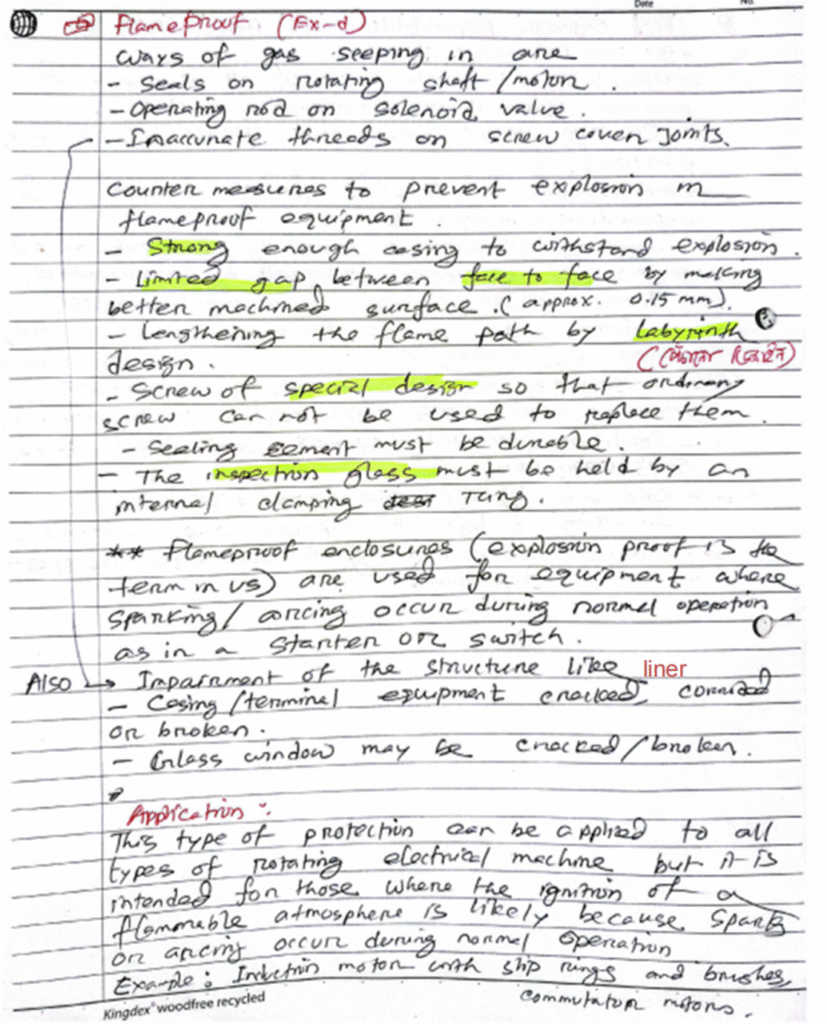
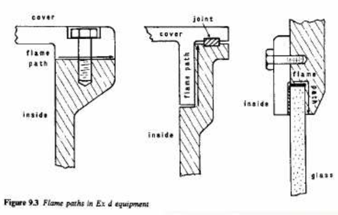
Ex-d: exd

.exd

Intrinsically Safe Equipment:

intrinsically safe equipment is defined as “equipment and wiring which is incapable of releasing sufficient electrical or thermal energy under normal or abnormal conditions to cause ignition of a specific hazardous atmospheric mixture in its most easily ignited concentration.”

Ex-I: Intrinsic Safety():

.ise  .intrinsically safe  .exi

Intrinsically safe equipment:

Electric arc or spark on flammable vapor increases the energy of the vapor and air locally so that particles are activated and creates a violent chemical reaction which is known an explosion. A weak spark does not have sufficient thermal energy to heat the local flammable mixture. Because energy generation rate is slower than energy dissipation rate. so no explosion occurs.

An intrinsically safe circuit is one that is designed for a power so low that any spark produced by it is incapable of igniting the flammable gas.

Intrinsically safe equipment uses such circuit. It is unable to produce strong enough spark to create explosion.

Intrinsically safe equipment is made into two standards. Ex-I(a) and Ex-i(b). Ex-i(a) is used in more hazardous area while Ex-i(b) used in less hazardous area. This method of protection is suitable for electrical supplies at less than 30 volts and 50 miliamps. It is used for instrumentation and control functions.

Design:

The equipment and system design in such a way that capacitance and inductance is kept minimum, to prevent storage of electrical energy which could generate spark. Ex-I devices cables are not permitted to keep in the same tray as other cables.

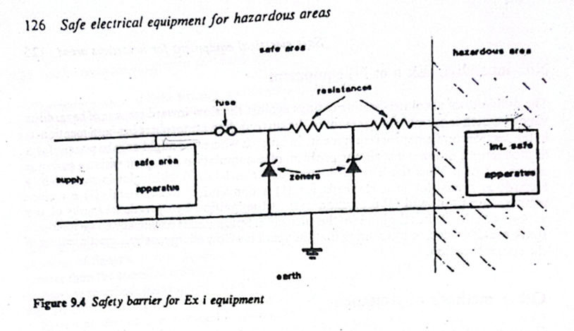
The whole system is earthed and protection is provided by shunt diode safety barriers between hazardous and non-hazardous area. The safety barriers have current limiting resistors and voltage by-passing Zener diodes to prevent excessive electrical energies from reaching the hazardous area. Intrinsically safe equipment is needed to be certified by administration.

Stroboscopic Effect: 

.stroboscopic effect .stoboscopic

The light falling on the moving parts of any machinery causes it to appear either running slow or in reverse direction or even may appear stationary. This effect is known as the stroboscopic effect.

Reason for Stroboscopic Effect:

In alternating current, for every cycle of current or voltage waves, the waves pass through zero-crossing twice. In our electrical system, we have lamps supplied with 50 Hz or 60 Hz AC supply.

Suppose we are supplying an AC supply of 50 HZ. This means that with a supply frequency of 50 Hz, the lamp will turn off 100 times per second because for 50 Hz supply the voltage or current waves passes through zero-crossings 100 times per second. But, due to the persistence of vision, our eyes do not notice this turning off phenomenon which leads to the stroboscopic effect.

Methods to Avoid Stroboscopic Effect

This pattern of illusions is not allowed in industries as this may lead to accidents. This is the main reason Fluorescent lamps are not preferred in industries.

However, this effect occurs in three-phase as well as single-phase supply. It can be avoided by some simple techniques.

Method to Avoid Stroboscopic Effect in Three-Phase Supply

If the system is supplied with a three-phase supply, adjacent lamps should be fed with a different phase so that the zero instants of the two lamps will not be the same.

Method to Avoid Stroboscopic Effect in Single-Phase Supply

If single-phase supply is only available, then the connection of two adjacent lamps is made such that the two lamps are connected in parallel with the supply.

In one lamp connection, a capacitor or condenser is kept in series with the choke. This makes a phase shift and eliminate the stroboscopic effect

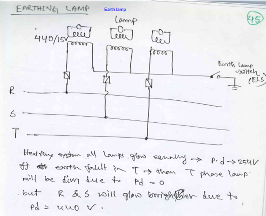
Finding Earth Fault on 220V Circuit

Finding an Earth Fault on a 220V circuit is comparatively difficult than a 440V circuit. The main reason being the lighting circuits found all round the vessel. However, any earth fault alarm with respect to a 220V circuit is usually treated as important but not an emergency.

  1. Check the trueness of the alarm.
  2. Isolate the complete Group start panel for a lighting division one by one.
  3. Check the Earth Fault indicator for status (still faulty or normal).
  4. If faulty, then put on the breaker which is put off earlier and isolate other group start panel for lighting circuit.
  5. Once the group start panel is identified, then individual lighting switches are turned off one by one and checked for the alarm condition.
  6. When any switch when turned off and thus the condition becomes normal, then this lighting circuit is marked and then inspection is done on the particular light for abnormalities.

Ingress of moisture is most common reason for an earth fault.

Alternate Idea: Instead of turning off breakers one by one for the lighting circuit, I followed a method where I turned off all lighting circuit of a particular doubted area. This method helps usually when there are two or more earth faults in 220V lighting circuit. By turning off all the breakers of a particular area, then switching on the breaker one by one will eliminate multiple earth faults.

When I turned off lighting switches one by one, it was difficult for me to identify multiple earth faults.

Once the particular faulty circuit is spotted, then we have to further break them into individual dividable pieces and check them for earth faults. For this as usual, we use megger against earth.

By removing fuse of the two phase lines, each line can be tested and the fault pinned down.

How to find out an Earth Fault?

.earth fault

The seriousness of the action to be taken on an Earth Fault depends on the part of the electrical system it affects. Conventional ships which operate on 3 Phase, 440V, have earth fault indicators installed on all three phases. Any earth fault on a 440V system is considered to be a serious trouble and immediate action is required to identify the faulty circuit. Any earth fault on 220V or any low voltage lighting circuit can be considered as important but need not require immediate attention. However, attention should be paid at the next earliest opportunity.

Finding Earth Fault on 440V circuit

  • Whenever there is an earth fault alarm, immediately inform to electrical officer (if he is on board).
  • First action is to check the trueness of the alarm. Usually there will be a test button which when pressed, resets the alarm and rechecks the condition of the earth fault.
  • If the ship is having IAS (Integrated Automation System), check on the computer in the list of events after which the alarm has activated.
  • If IAS facility is not available, there is only one option of isolating each and every machinery in the 440 V circuit and check whether the earth fault indication returns back to normal.
  • Isolation of all machinery, which operates on 440V, is not always possible. Certain critical equipment like steering gear and lubricating oil pumps cannot be isolated for when the ship is underway. However changeover can be done from running machinery to the standby one and thus the earth fault can be found.

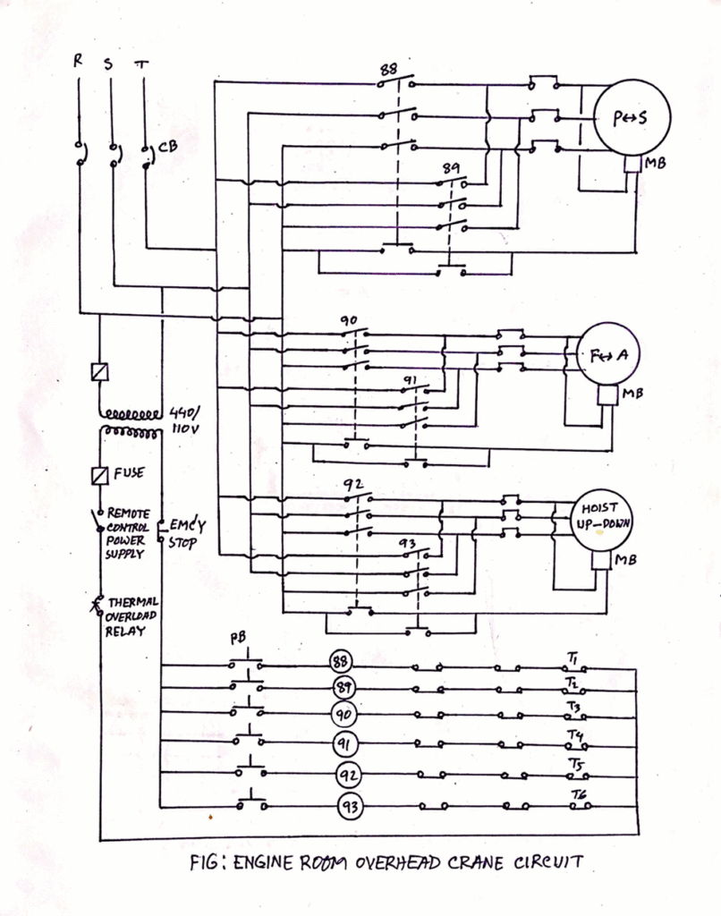
A General Overview of Engine Room Crane and Safety Features

The engine room crane consists of a motor coupled with wire drum so that the motor can lift or lower the crane hoist by winding or unwinding the wire over the drum. The whole system is then fitted in a trolley.

Two pathways are built with a rack and pinion arrangement, both in transverse and longitudinal direction of the engine room and over the main engine, where the trolley is placed so that the whole unit can move fore-aft and port starboard.

A remote is provided so that the crane can be operated from any position, thus allowing the user to keep a safe distance from the lifted load. It is the duty of the responsible engineer onboard to operate the crane and to have regular checks on the safety and working of the crane. Second engineer is responsible for operation, maintenance, and safety checks of the engine room crane.

Safety Features of Engine Room Crane:

.ohcs

1) The most important safety feature of the crane is the electromagnetic fail-safe brakes which do not allow the crane to fall with the load even when there is failure of power. For this:

– Normally centrifugal brakes are fitted inside the rotating drum.

– The brake pads are always in applied state and pushed by magnetic springs when not in operation or when there is a power failure.

– As the crane is operated or the power is supplied, the spring gets pulled inward or compressed due to the electromagnetic effect of the current. This allows the crane to be operated normally.

2) Emergency stop is provided in the remote so that the operator can stop the crane at any time.

3) The motor is fitted with distance limit switch in both transverse and longitudinal direction so that the travel of the trolley limited and hence crane should not overshoot the rack’s end.

4) Mechanical stoppers are provided for both directions in case the electrical distance limit trips fail.

5) The up and down travel of the hook is also attaches with automatic stopper to avoid overloading of the motor.

6) The motor is fitted with thermal protection trip. When the motor windings get overheated, trip will activate saving the motor winding from burning.

7) Load limit switch is also fitted which will trip the motor if the load to be lifted is above the crane capacity.

Operational safety checks

1) It’s the responsibility of senior officers to operate the crane and to make sure all the personnel involve in any lifting operation are at a safe distance during operation of the crane.

2) Additional tools like eye-bolts, shackle, wire sling, belts etc. used for lifting must be checked before use.

3) It should be noted that no one walks or stand below the crane when it is in the loaded condition.

1) Daily checks

  • Check the lubrication
  • Check the noise level by operating the crane without load
  • Check the heat generation
  • Check all the limits and trips are working properly
  • Check the contact areas of electrical equipment
  • Check the brake operation
  • Check condition of clamp in the hook

2) PMS

  • Overhauling of motor
  • Greasing of wires
  • Renewal of wire ropes
  • Annual survey
  • Load test
  • Grease: Wire ropes, rollers, plain bearings are applied with grease for smooth working.
  • Oil: Lube oil is used for lubrication of ball bearing and roller bearing of hoisting and slewing gears. Check the oil level regularly and replenish once the level is below the mark.
  • Inspect the wire rope for twisting, any unstable, any fracture
  • Inspect The Gears: for any noise, damage on teeth
  • Check Condition Of Sheave/pulley
  • Hook condition
  • Brake condition: The engine room crane is equipped with electromagnetic brake with fail-safe arrangement. This is the most important safety arrangement provided in the crane.

Mandatory High Voltage Safety Equipment:

Mandatory High Voltage Instruments for Ships

Safety Equipment:

  • Personal protective equipment (PPE) including insulated gloves, safety goggles, and arc flash protective clothing
  • Insulated tools specifically designed for high voltage work

Testing and Measurement Devices:

  • High voltage test probes and multimeters
  • Insulation resistance testers capable of measuring high voltage equipment
  • Polarization Index (PI) testing equipment

Note on Polarization Index:

PI testing equipment is designed to measure the insulation resistance of electrical systems over time. The test involves applying a high DC voltage to the insulation and measuring the resistance at specific intervals, typically at 1 minute and 10 minutes. The ratio of these two measurements provides the Polarization Index, which helps evaluate the quality and deterioration of the insulation

Safety and Isolation Tools:

  • Voltage detectors to verify the absence of voltage before work
  • Earthing devices for isolating equipment
  • Locking devices and safety tags for isolation procedures

Diagnostic Equipment:

  • Partial discharge detectors for insulation testing.
  • Thermal imaging cameras for identifying potential hotspots

Documentation and Training Aids:

  • High voltage safety manuals and procedures
  • Switching strategy documentation
  • High voltage simulator for training purposes (recommended but not mandatory)

Note: All high voltage instruments must be properly calibrated, maintained, and used only by qualified personnel. Regular inspections and testing of these instruments are essential to ensure their reliability and the safety of the crew working with high voltage systems onboard.

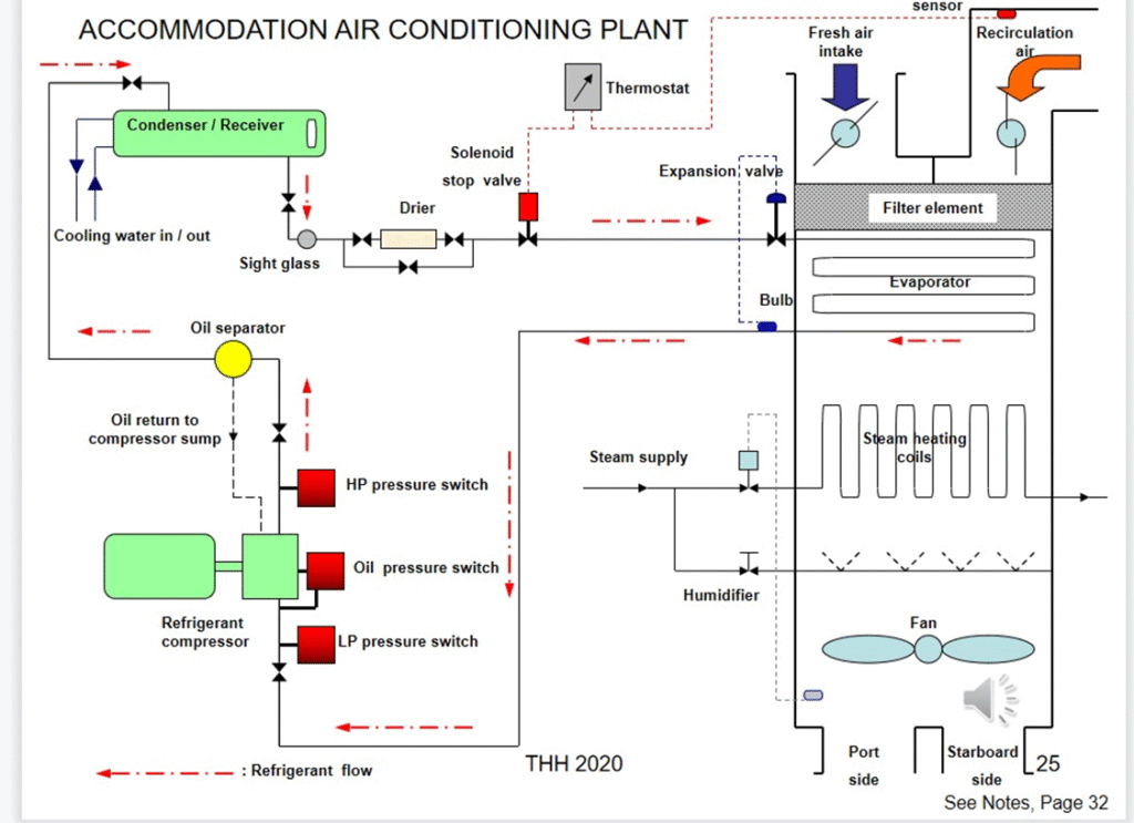
AC Plant:

.ac plant   .air conditioning

Brief explanation:

Temp – com outlet- 70-90, condenser outlet- 38-45, TXV out- 0-10, evaporator out-7-15,
Superheat- evaporator outlet 5-6 and compressor inlet around 10 degree

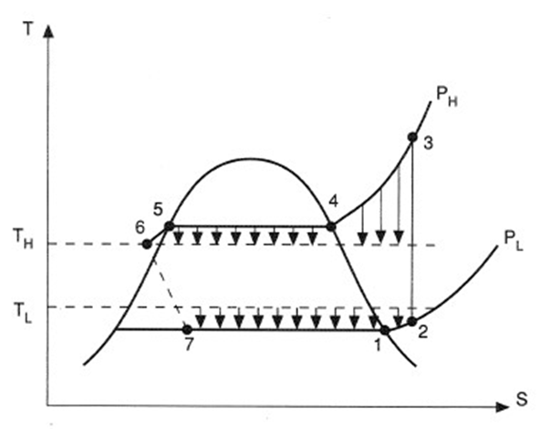
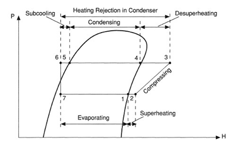
Figure 4. T-S diagram for basic vapor compression cycle.


The cycle processes can be described as follows:
7-1 Evaporation of the liquefied refrigerant at constant temperature T1 = T7.
1-2 Superheating of the vapor from temperature T1 to T2 at constant pressure PL.
2-3 Compression (not necessarily adiabatic) from temperature T2 and pressure PL to temperature T3 and pressure PH.
3-4 Cooling of the super-heated vapor to the saturation temperature T4.
4-5 Condensation of the vapor at temperature T4 = T5 and pressure PH.
5-6 Subcooling of the liquid from T5 to T6 at pressure PH.
6-7 Expansion from pressure PH to pressure PL at constant enthalpy.
A further difference between the real cycle and the ideal is that temperature T1 at which evaporation takes place is lower than the temperature TL of the cold region so heat transfer can take place. Similarly the temperature T4 of the heat rejection must be higher than the hot region temperature TH to bring about heat transfer in the condenser.
It is usual for the vapor-compression cycle to be plotted on a pressure-enthalpy (p-h) diagram as shown in


Figure 5. p-h representation of vapor compression cycles.


types of fault

  1. Loss of oil from crankcase
  2. Excessive amount of oil in the crankcase
  3. Refrigerant leakages
  4. Refrigerant undercharged
  5. Refrigerant overcharged
  6. Fall off in refrigerating effect
  7. Short cycling on HP cut out
  8. Short cycling on LP cut out
  9. Moisture in the system
  10. Air in the system
  11. Frost on evaporator coils
  12. Compressor drawing in refrigerant liquid
  13. Noisy compressor
  14. Poor cooling in condenser

“Loss of oil” from the crankcase:

1.1) Low crankcase oil level – operational leakages.   
1.2) Foaming – sudden “disappearance” of oil.

Operational Leakages due to malfunction of the mechanical seals resulting :

a) Loss of oil.

b) Loss of refrigerant – the end clearance of the piston/scraper rings allows  a small amount of refrigerant gas to reach the crankcase

 1.2) Foaming can happen when –

a) Pressure drops rapidly in the evaporator.

b) Compressor high capacity to pull down pressure rapidly.

c) Crankcase space developing a low pressure condition.

With the formation of Low Pressure within the crankcase space :

 – lubricating oil is unable to hold the small bubbles in the oil.

 – small bubbles enlarge , attain buoyancy

 – bubbles raise to the oil surface

Excessive amount of oil in the crankcase   

Do not top up the oil level in the crankcase to excessive high level. It may cause :

  • Overloading of the OIL SEPARATOR
  • Oil passing to the condenser and the rest of system – hampering optimum heat transfer.
  • Always maintain the oil level at the recommended level as indicated on the sight glass.
Indication of refrigerant leakages:
  • Low refrigerant level in sight glass
  • Large bubbles in sight glass
  • Oil weeping at joint and connection
  • Relative lower pressure readings across the system (LP,OP & HP)
  • High superheat at compressor suction
  • Compressor running continuously – room temperature not reducing
Fall off in refrigerating effect (over a short period)
  • Refrigerant loss through valve stem gland packing, pipes, fittings compressor etc
  • Broken suction, discharge valves of compressor
  • Belt slipping – motor to compressor
  • Icing of expansion valve
HP cut out
  • Insufficient or intermittent water flow for condenser cooling
    • Relatively higher temperature of cooling water
    • Scaled or fouled condenser
    • Overcharging of refrigerant
    • Air in the system
Short cycling on LP cut out
  • Malfunction LP pressure switch
  • Evaporator coils heavily frosted
  • Strainer for TEV chocked
  • Leaky discharge valves
  • Deflective expansion valve
  • Refrigerant undercharge
Refrigerant undercharged
  • Large bubbles noted in sight glass
  • Lower LP , OP , HP pressure
  • Continuous running of compressor- room temperature not reducing
  • Relative less frosting on compressor suction line/valve
  • System performance drops
Refrigerant overcharged
  • Sight glass refrigerant level higher than normal
  • Higher LP/OP/HP pressure
  • Compressor stopping on HP cutout
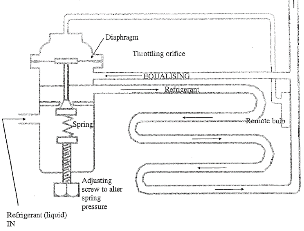
  • Severe frosting on compressor suction line/valve – Malfunction of TEV
Moisture in the system
  • Frosting on inlet side of expansion valve
  • Low LP pressure
  • Corrective Actions : Renew the filter/drier.

Water (not removed by the filter/Drier) if present with the refrigerant at the

  • TEV will become ice – restricting proper refrigerant flow.

In a good working order refrigeration system, a thin layer of ice of about 2-4mm will be formed on the TEV (external body). The ice formation is due to the unavoidable “flash off” of liquid refrigeration when it passes through the orifice. The presence of an extra volume of ice formation on the TEV indicates that Excessive flash off is taking place.

Frost on evaporator coils
  • Compressor runs longer
  • Short cycling on LP switch
  • Performance drops
  • Low suction pressure – Refrigerant temperature drops to 0 degree celsius or lower

Frost coming back in evaporator coil continuously because of relative lower pressure existing in the coils. The low pressure could be due to refrigerant leakages, dirty filter/drier, dirty strainer of the TEV – any reasons that results in a lower than normal pressure within the coils. The pressure of the refrigerant directly affects the temperature of the refrigerant in the coil. The lower the pressure  – the lower will be the temperature of the refrigerant. If the temperature of the refrigerant is near to or lower than or at the freezing point of water, high relative humidity air flowing pass the evaporator coil will cause ice to be built up persistently.

Remedy : Restore the working pressure of the LP side to the marker’s recommended value – bring the operating temperature of the refrigerant away from the freezing point of water.

Compressor drawing in refrigerant liquid

      Usually is due to malfunction of TEV resulting :

  • Excessive frosting at inlet valve body of the compressor and/or icing on the cylinder head.
  • Oil level at compressor sump reduced
  • High suction pressure
  • Noisy compressor operation
Noisy compressor
  • Liquid knock / hammering*
  • Lack of lubrication
  • Internal components damaged
Air in the system
  • High condenser pressure (HP pressure)
  • Jumping of pressure gauges pointer
  • Compressor noisy
  • Small bubbles at sight glass
  • Relative small difference in cooling water in & out temperature – Less heat transfer  

Air (or moisture) can be accidentally introduced into the refrigeration system during topping up of refrigerant into system or during topping up of lubrication oil for the compressor.

Air will finally be accumulated in the condenser.

1) Mainly nitrogen(78%) and oxygen(21%) – it is not possible to condense air with the cooling water.

2) The volume of air will occupy the space at the top of the condenser –

     a) prevents refrigerant gas entering the condenser.

     b) reduces the total cooling surface area for the refrigerant.

3) Result in

(a) higher pressure reading in the HP side of the system and

 (b) reduction in temperature differential of the cooling water.Cooling water inlet temperature minus outlet temperature.

Removal of Air :

1) Connect a refrigerant recovery bottle to the purging cock (of the condenser) via a flexible hose.

2) Remove the air until the flexible hose is cold or/and the cooling water difference temperature of about
    8-10 degree Celsius is achieved.

Note : The refrigerant used although do not contribute to ozone depletion , it is still a greenhouse gas Therefore , it should not be released directly into the atmosphere


Master solenoid valve


The master solenoid is installed after the receiver, which is controlled by the control unit. In case of sudden stoppage of the compressor, the master solenoid also closes, avoiding the flooding of the evaporator with refrigerant liquid