Single Phasing

.Single Phasing

Causes:
(1) Due to loose connection in any one phase of the supply system.
(2) Due to loose connection in any one phase of the motor terminal.
(3) Due to open circuit in any one phase of the supply system.
(4) Due to open circuit in any one phase of the motor winding.
(5) Due to short circuit in one phase of the star connected or delta connected motor.
(6) Due to equipment failure of supply system.
(7) One or more, out of the 3 back up fuse blows or fuse wire melts (if the fuse is of wire type)
(8) A wrong or improper setting of any other protection devices provided on the motor can also lead to single phasing.

How to detect:
(1) Unusual humming noise coming from the motor.
(2) The motor is vibrating at a higher frequency than usual.
(3) The smell of hot or burnt copper
(4) Visible light smoke & fumes from motor casing.
(5) Higher amperage of the motor

Effects:
(1) If the motor is in stopped condition, it can’t be started due to single phasing. Also due to the safety system provided in 3-phase motor to protect it from overheating.
(2) If single phasing occurred while the motor is operating, it will continue to run because of the torque produced by the remaining two phases, which is produced as per the demand by the load. As the remaining two phases are doing additional work, they will be overheated which might result in critical damage to the windings.
(3) It will lead to increase in the current flow 2.4 times the average current value in the remaining two phases.
(4) Single phasing reduces the speed of the motor and its rpm will fluctuate.
(5) Almost all the motor system in the ship has st-by arrangement. If the motor is selected for st-by, with single phasing problem – it will not start in emergency which will lead to failure of the related system.
(6) If the problem is not identified and motor running continues; windings will melt due to overheating or can lead to short circuit or earthing.
(7) In such condition, if the crew of the ship comes in contact with the motor, he will get an electrical shock. Which can even be fatal.
(8) It may cause overloading of generator
(9) Abnormal noise and Vibration.

Protection devices:
(1) Electromagnetic overload device.
(2) Thermistor; sends signals to the amplifiers – detects overheat due to over current flow.
(3) Bi metal strips.
(4) Standard motor starter overload protection.

All motors above 500 kW are to be provided with protection devices or equipment to prevent any damage due to single phasing. But this rule doesn’t apply to the motor of steering gear system of the ship.
Only an alarm will be sounded for detection of the single phasing.

But the motor will not stop as the continuous operation of S/G system is essential for safety & propulsion of the ship.
Especially when the vessel is in congested waters or under maneuvering.

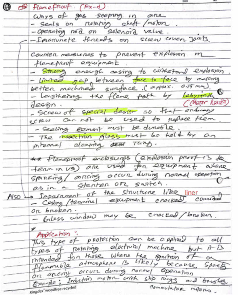
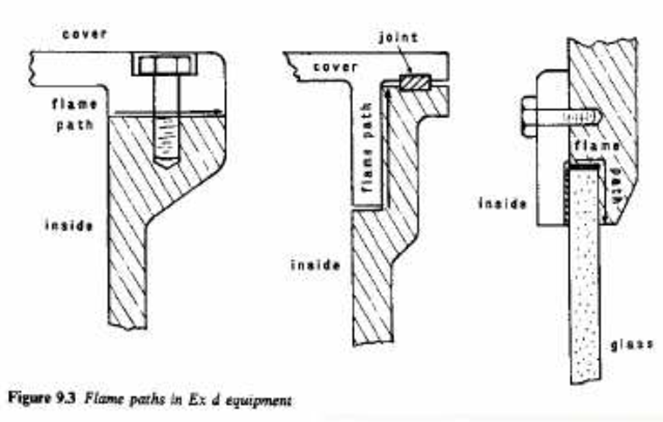
Ex-d: exd

.exd

Intrinsically Safe Equipment:

intrinsically safe equipment is defined as “equipment and wiring which is incapable of releasing sufficient electrical or thermal energy under normal or abnormal conditions to cause ignition of a specific hazardous atmospheric mixture in its most easily ignited concentration.”

Ex-I: Intrinsic Safety():

.ise  .intrinsically safe  .exi

Intrinsically safe equipment:

Electric arc or spark on flammable vapor increases the energy of the vapor and air locally so that particles are activated and creates a violent chemical reaction which is known an explosion. A weak spark does not have sufficient thermal energy to heat the local flammable mixture. Because energy generation rate is slower than energy dissipation rate. so no explosion occurs.

An intrinsically safe circuit is one that is designed for a power so low that any spark produced by it is incapable of igniting the flammable gas.

Intrinsically safe equipment uses such circuit. It is unable to produce strong enough spark to create explosion.

Intrinsically safe equipment is made into two standards. Ex-I(a) and Ex-i(b). Ex-i(a) is used in more hazardous area while Ex-i(b) used in less hazardous area. This method of protection is suitable for electrical supplies at less than 30 volts and 50 miliamps. It is used for instrumentation and control functions.

Design:

The equipment and system design in such a way that capacitance and inductance is kept minimum, to prevent storage of electrical energy which could generate spark. Ex-I devices cables are not permitted to keep in the same tray as other cables.

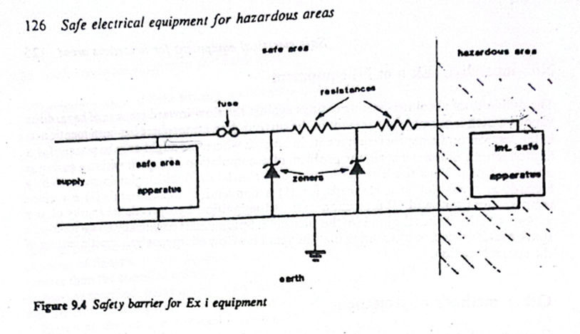
The whole system is earthed and protection is provided by shunt diode safety barriers between hazardous and non-hazardous area. The safety barriers have current limiting resistors and voltage by-passing Zener diodes to prevent excessive electrical energies from reaching the hazardous area. Intrinsically safe equipment is needed to be certified by administration.

Stroboscopic Effect: 

.stroboscopic effect .stoboscopic

The light falling on the moving parts of any machinery causes it to appear either running slow or in reverse direction or even may appear stationary. This effect is known as the stroboscopic effect.

Reason for Stroboscopic Effect:

In alternating current, for every cycle of current or voltage waves, the waves pass through zero-crossing twice. In our electrical system, we have lamps supplied with 50 Hz or 60 Hz AC supply.

Suppose we are supplying an AC supply of 50 HZ. This means that with a supply frequency of 50 Hz, the lamp will turn off 100 times per second because for 50 Hz supply the voltage or current waves passes through zero-crossings 100 times per second. But, due to the persistence of vision, our eyes do not notice this turning off phenomenon which leads to the stroboscopic effect.

Methods to Avoid Stroboscopic Effect

This pattern of illusions is not allowed in industries as this may lead to accidents. This is the main reason Fluorescent lamps are not preferred in industries.

However, this effect occurs in three-phase as well as single-phase supply. It can be avoided by some simple techniques.

Method to Avoid Stroboscopic Effect in Three-Phase Supply

If the system is supplied with a three-phase supply, adjacent lamps should be fed with a different phase so that the zero instants of the two lamps will not be the same.

Method to Avoid Stroboscopic Effect in Single-Phase Supply

If single-phase supply is only available, then the connection of two adjacent lamps is made such that the two lamps are connected in parallel with the supply.

In one lamp connection, a capacitor or condenser is kept in series with the choke. This makes a phase shift and eliminate the stroboscopic effect

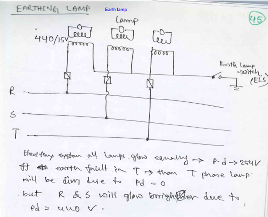
Finding Earth Fault on 220V Circuit

Finding an Earth Fault on a 220V circuit is comparatively difficult than a 440V circuit. The main reason being the lighting circuits found all round the vessel. However, any earth fault alarm with respect to a 220V circuit is usually treated as important but not an emergency.

  1. Check the trueness of the alarm.
  2. Isolate the complete Group start panel for a lighting division one by one.
  3. Check the Earth Fault indicator for status (still faulty or normal).
  4. If faulty, then put on the breaker which is put off earlier and isolate other group start panel for lighting circuit.
  5. Once the group start panel is identified, then individual lighting switches are turned off one by one and checked for the alarm condition.
  6. When any switch when turned off and thus the condition becomes normal, then this lighting circuit is marked and then inspection is done on the particular light for abnormalities.

Ingress of moisture is most common reason for an earth fault.

Alternate Idea: Instead of turning off breakers one by one for the lighting circuit, I followed a method where I turned off all lighting circuit of a particular doubted area. This method helps usually when there are two or more earth faults in 220V lighting circuit. By turning off all the breakers of a particular area, then switching on the breaker one by one will eliminate multiple earth faults.

When I turned off lighting switches one by one, it was difficult for me to identify multiple earth faults.

Once the particular faulty circuit is spotted, then we have to further break them into individual dividable pieces and check them for earth faults. For this as usual, we use megger against earth.

By removing fuse of the two phase lines, each line can be tested and the fault pinned down.

How to find out an Earth Fault?

.earth fault

The seriousness of the action to be taken on an Earth Fault depends on the part of the electrical system it affects. Conventional ships which operate on 3 Phase, 440V, have earth fault indicators installed on all three phases. Any earth fault on a 440V system is considered to be a serious trouble and immediate action is required to identify the faulty circuit. Any earth fault on 220V or any low voltage lighting circuit can be considered as important but need not require immediate attention. However, attention should be paid at the next earliest opportunity.

Finding Earth Fault on 440V circuit

  • Whenever there is an earth fault alarm, immediately inform to electrical officer (if he is on board).
  • First action is to check the trueness of the alarm. Usually there will be a test button which when pressed, resets the alarm and rechecks the condition of the earth fault.
  • If the ship is having IAS (Integrated Automation System), check on the computer in the list of events after which the alarm has activated.
  • If IAS facility is not available, there is only one option of isolating each and every machinery in the 440 V circuit and check whether the earth fault indication returns back to normal.
  • Isolation of all machinery, which operates on 440V, is not always possible. Certain critical equipment like steering gear and lubricating oil pumps cannot be isolated for when the ship is underway. However changeover can be done from running machinery to the standby one and thus the earth fault can be found.

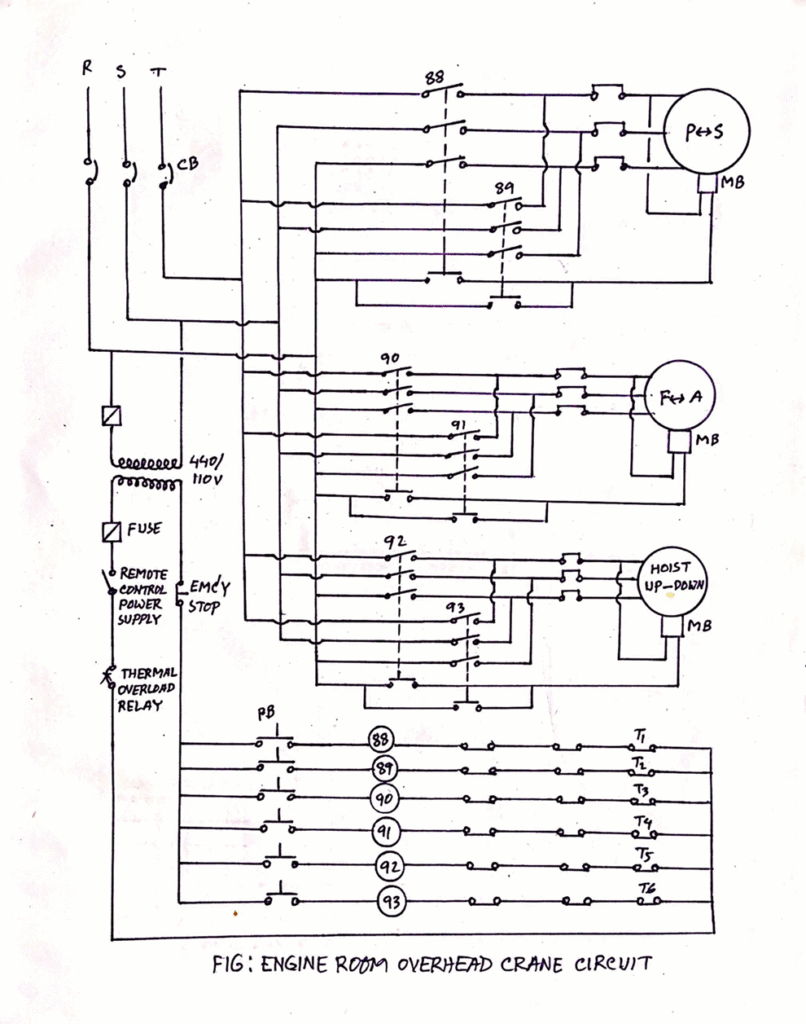
A General Overview of Engine Room Crane and Safety Features

The engine room crane consists of a motor coupled with wire drum so that the motor can lift or lower the crane hoist by winding or unwinding the wire over the drum. The whole system is then fitted in a trolley.

Two pathways are built with a rack and pinion arrangement, both in transverse and longitudinal direction of the engine room and over the main engine, where the trolley is placed so that the whole unit can move fore-aft and port starboard.

A remote is provided so that the crane can be operated from any position, thus allowing the user to keep a safe distance from the lifted load. It is the duty of the responsible engineer onboard to operate the crane and to have regular checks on the safety and working of the crane. Second engineer is responsible for operation, maintenance, and safety checks of the engine room crane.

Safety Features of Engine Room Crane:

.ohcs

1) The most important safety feature of the crane is the electromagnetic fail-safe brakes which do not allow the crane to fall with the load even when there is failure of power. For this:

– Normally centrifugal brakes are fitted inside the rotating drum.

– The brake pads are always in applied state and pushed by magnetic springs when not in operation or when there is a power failure.

– As the crane is operated or the power is supplied, the spring gets pulled inward or compressed due to the electromagnetic effect of the current. This allows the crane to be operated normally.

2) Emergency stop is provided in the remote so that the operator can stop the crane at any time.

3) The motor is fitted with distance limit switch in both transverse and longitudinal direction so that the travel of the trolley limited and hence crane should not overshoot the rack’s end.

4) Mechanical stoppers are provided for both directions in case the electrical distance limit trips fail.

5) The up and down travel of the hook is also attaches with automatic stopper to avoid overloading of the motor.

6) The motor is fitted with thermal protection trip. When the motor windings get overheated, trip will activate saving the motor winding from burning.

7) Load limit switch is also fitted which will trip the motor if the load to be lifted is above the crane capacity.

Operational safety checks

1) It’s the responsibility of senior officers to operate the crane and to make sure all the personnel involve in any lifting operation are at a safe distance during operation of the crane.

2) Additional tools like eye-bolts, shackle, wire sling, belts etc. used for lifting must be checked before use.

3) It should be noted that no one walks or stand below the crane when it is in the loaded condition.

1) Daily checks

  • Check the lubrication
  • Check the noise level by operating the crane without load
  • Check the heat generation
  • Check all the limits and trips are working properly
  • Check the contact areas of electrical equipment
  • Check the brake operation
  • Check condition of clamp in the hook

2) PMS

  • Overhauling of motor
  • Greasing of wires
  • Renewal of wire ropes
  • Annual survey
  • Load test
  • Grease: Wire ropes, rollers, plain bearings are applied with grease for smooth working.
  • Oil: Lube oil is used for lubrication of ball bearing and roller bearing of hoisting and slewing gears. Check the oil level regularly and replenish once the level is below the mark.
  • Inspect the wire rope for twisting, any unstable, any fracture
  • Inspect The Gears: for any noise, damage on teeth
  • Check Condition Of Sheave/pulley
  • Hook condition
  • Brake condition: The engine room crane is equipped with electromagnetic brake with fail-safe arrangement. This is the most important safety arrangement provided in the crane.

Mandatory High Voltage Safety Equipment:

Mandatory High Voltage Instruments for Ships

Safety Equipment:

  • Personal protective equipment (PPE) including insulated gloves, safety goggles, and arc flash protective clothing
  • Insulated tools specifically designed for high voltage work

Testing and Measurement Devices:

  • High voltage test probes and multimeters
  • Insulation resistance testers capable of measuring high voltage equipment
  • Polarization Index (PI) testing equipment

Note on Polarization Index:

PI testing equipment is designed to measure the insulation resistance of electrical systems over time. The test involves applying a high DC voltage to the insulation and measuring the resistance at specific intervals, typically at 1 minute and 10 minutes. The ratio of these two measurements provides the Polarization Index, which helps evaluate the quality and deterioration of the insulation

Safety and Isolation Tools:

  • Voltage detectors to verify the absence of voltage before work
  • Earthing devices for isolating equipment
  • Locking devices and safety tags for isolation procedures

Diagnostic Equipment:

  • Partial discharge detectors for insulation testing.
  • Thermal imaging cameras for identifying potential hotspots

Documentation and Training Aids:

  • High voltage safety manuals and procedures
  • Switching strategy documentation
  • High voltage simulator for training purposes (recommended but not mandatory)

Note: All high voltage instruments must be properly calibrated, maintained, and used only by qualified personnel. Regular inspections and testing of these instruments are essential to ensure their reliability and the safety of the crew working with high voltage systems onboard.