Aft End Structure:

.aft structure .aft end structure .aftend structure .aft end construction .aft construction   .aec

Considerable attention is paid to the overall design of the stern in order to improve flow into and away from the propeller. There are two types of stern. Cruiser stern, Transom stern. Cruiser stern used previously, but today most of these vessels have a transom stern. A cruiser stern presents a more pleasant profile and is hydrodynamically efficient, but the transom stern offers a greater deck area aft, is a simpler construction, and can also provide improved flow around the stern. Many forms of rudder are available, depending on the manoeuvering needs. Both the shape of the stern and the rudder type will determine the form of the stern frame, and this will be further influenced by the required propeller size. The propeller shaft and the rudder stock  pierce the intact watertight hull, so particular attention should be given. The safety of the ship may depend on these arrangements.

Stern Construction:

.Stern Construction

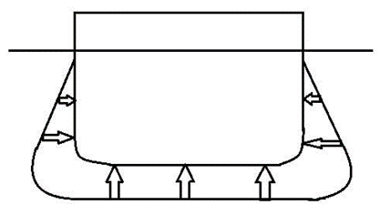
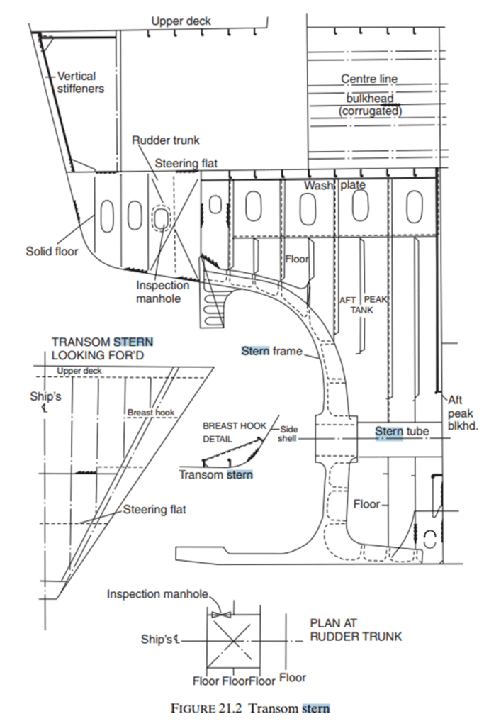
Flat stern plating stiffened with vertical stiffeners. Deep floors and a centre line girder are provided at the lower region of the transom stern construction. Panting arrangements at the aft end are provided.

Stern Frame

.stern frame construction   .sfc

The form of the stern frame is influenced by the stern profile and rudder type. To prevent serious vibration at the after end there must be adequate clearances between the propeller and stern frame, and this determines its overall size.

The stern frame of a ship may be cast, forged, or fabricated from steel plate and sections. On larger ships it is generally either cast or fabricated,
the casting done by a specialist works outside the shipyard. Larger stern frames cant be casted easily due to its bigger size. Also the transportation is a problem .So it may be cast in more than one piece and then welded together after bringing the pieces to the shipyard. Fabricated stern frames are produced by the shipyard itself, plates and bars being welded together to produce the stern frame.

 Forged stern frames are also produced by a specialist manufacturer. And may also be made in more than one piece where the size is excessively large or shape is complicated. Sternpost sections are made streamlined form, in order to prevent eddies being formed behind the posts. Eddies can lead to an increase in the hull resistance.

Welded joints in cast steel sections will need careful preparation and preheating. Both the cast and fabricated sections are supported by horizontal webs. The connection of the stern frame to the hull structure is very important, the rotating propeller supported by the stern frame may set up serious vibrations. The rudder post is carried up into the main hull and connected to the transom floor which has an increased plate thickness. Also the propeller post may be extended into the hull and connected to a deep floor, the lower sole piece is carried forward and connected to the keel plate. Side shell plates are directly welded to the stern frame.

Fore end structure: FWD Construction, Forward Construction

.FWD Construction .forward construction .fwdc .fore end construction

  • FWD construction is forward of the collision bulkhead.
  • The chain locker is included as it is usually fitted forward of the collision bulkhead below the second deck or upper deck, or in the forecastle itself
  • On the forecastle deck the heavy windlass seating is securely fastened and given considerable support. The deck plating thickness is increased locally, and smaller pillars with heavier beams and a centre line pillar bulkhead, may be fitted below the windlass.

Stem

  • On many conventional ships a stem bar, which is a solid round bar, is fitted from the keel to the waterline region, and a radiused plate is fitted above the waterline to form the upper part of the stem.
  • This forms a ‘soft nose’ stem, which in the event of a collision will buckle under load, keeping the impact damage to a minimum.
  • The solid round bar is welded inside the keel plate at its lower end, and inside the radiused stem plate at its upper end,
  • the shell is welded each side to the radiused plate.
  • breast hooks’ is used to support that part of the stem which is formed by radiused plates between the decks and below the lowest deck, to reduce the unsupported span of the stem.
  • Panting stringer provided to counteract the panting stress. Panting stringer are triangular shape. Panting stringer are situated 2 meter above the keel and every 2 meter apart one panting stringer is fitted.
  • Where the plate radius is large, further stiffening is provided by a vertical stiffener on the centre line.
  • The thickness of these plates is greater than the forward side shell, but the thickness may taper near the side shell at the stem head.

Floors and Different Types of Floors

   Unlike structures on land where a floor refers to something horizontal that you can stand on, floors on ships are the transverse stiffeners mounted vertically on the ship’s bottom. Floor structure is continuous from the centre to the side plating and supports the inner shell (tank top). They may either be solid plates (no cut holes except small half round drain holes at the bottom part) or plates with cut lightening holes.

Solid Floors

 It is the easiest to comprehend, and consists of a solid plate, with no lightening holes cut into it (they lessen the weight of the plate and allow for the free flow of any liquids stored in the space). Normally it form a tank, below watertight bulkheads these floors are using

Plate Floor

Plate Floor is the one if the stiffener / floor plate is made of a solid plate with openings. This is done to optimize weight and also to allow free flow of fluids based on the purpose of the floor plate / part of the ship (Like a tank)

Bracket Floor

Bracket floor is the one if the stiffener / floor plate is made of a built-up section with a large opening. This is also done to optimize the weight, provided where much strength / structural integrity is not required and also on the purpose of the area of the ship

Ship floor:

.ship floor .ship floor .floor construction .plate floor

Ship floor construction:

Double bottom, transversely framed floor construction:

→this type of floor construction used in ships of length less than 120 meters.

Vertical transverse plate floors are provided both where the bottom is transversely and longitudinally framed.

→Watertight and oiltight plate floors are provided → At the ends of bottom tank spaces and under the main bulkheads

→ These are made watertight or oiltight by closing any holes in the plate floor and welding collars around any members which pass through the floors.

→The bracket floors form the transverse stiffeners at every frame, and

→solid plate floors are used at every 3 to 4 frame space, or 1.8 meters intervals, to strengthen the bottom transversely and support the inner bottom

intercostal side girders

→ run longitudinally fastening the transverse members of the floor,

→ it reduces the span of the plates.

→Side girders are continuous members,

→where there is an intersection between a plate floor and a side girder,

→the plate floor is cut and welded on both the sides of the girder

→ it is done to reduce the span of the plate floors,

→ the girders will act as supporting members to the plate floors.

→ Keels are flat plated.

→Intercostal girders or side girders, and plate floors

→ will have lightning holes at regular intervals to reduce the structural weight and

→will have flanged manholes to provide access.

→ Plate floors have drain holes to help drainage of liquids.

→Plate floors are

→further stiffened by flat bar stiffeners, and bracket floors, by angle struts to prevent warping.

Stresses in Ships

Stresses in Ships

.stresses in ship    .stress on ship    .stress in ship    .stresses on ship

A ship at sea is subjected to a number of forces causing the structure to distort. Initially, these may be divided into two categories, as follows:

Static forces –

 Ship floating at rest in still water.

Two major forces acting:

  • the weight of the ship acting vertically down
  • buoyancy acting up

Dynamic forces – 

due to the motion of the ship and the sea the structural stresses, caused by the above forces, to which the ship structure is subjected may be categorized as:

  1. Longitudinal stresses (hogging and sagging)
  2. Transverse stresses (racking and the effects of water pressure)
  3.  Local dynamic stresses (panting and pounding)

Longitudinal Stress

  • The forces are two in number, the weight of the ship and all that it carries acting downwards and the vertical component of the hydrostatic pressure.
  • Depending upon the direction in which the bending moment acts the ship will Hog or Sag.
Hogging
  • If the buoyancy amidships exceed the weight due to loading or when the wave crest is amidships, the ship will Hog, as a beam supported at mid length and loaded at the end.

Sagging

  • If the weight amidships exceed the buoyancy or when the wave trough amidships the ship will sag, as a beam supported at a ends and loaded at mid length.

TRANSVERSE STRESSES

Racking

When a ship is rolling in a seaway or is struck by beam waves, the ship’s structure is liable to distort in a transverse direction as shown.

Water Pressure

Water pressure acts perpendicular to the shell of the ship, increasing with depth. The effect is to push the ship’s sides in and the bottom up. It is resisted by frames, bulkheads, floor and girders.

LOCAL DYNAMIC STRESSES


The dynamic effects arise from the motion of the ship itself. A ship among waves as three linear motions.

  1. Surging: The forward and aft linear motion (along x) of a ship is called surging.
  2. Heaving: The vertical up and down linear motion (along y) of a ship is called heaving.
  3. Swaying: The side to side linear motion (along z) of a ship is called swaying.
  4. Rolling: The rotational motion of a ship about longitudinal axis is called rolling.
  5. Yawing: The rotational motion of a ship about vertical axis is called yawing.
  6. Pitching: The rotational motion of a ship about transverse axis is called pitching.

When the ship motions are large particularly in pitching and heaving, considerable dynamic forces can be created in the structure.

Panting

.panting

As wave passes along the ship, they cause fluctuation in water pressure which tends to create in and out movement of the shell plating This in and out movement is called panting.

This is particularly the case at the fore end. The rules of the classification societies required extra stiffening, at the end of the ship, in the form of beams, brackets, stringer plate, etc. in order to reduce the possibility of damage.

Slamming or Pounding

.pounding

In heavy weather when the ship is heaving and pitching the bows often lift clear of the water and then slam down heavily onto the sea, which is called pounding.

Extra stiffening require at the fore end to reduce the possibility of damage.