Thrust Bearing:

.thrust bearing

Article link: https://www.marinesite.info/2013/12/thrust-bearing.html

  • The thrust from the propeller is taken up by the main thrust bearing, which transmits the thrust to the ship’s hull and causes the ship to be propelled in the direction of the thrust.
  • The thrust bearing is always fitted at the aft end of the main engine crankshaft. The main thrust bearing controls the correct location of the crank pins relative to the center of the cylinders.
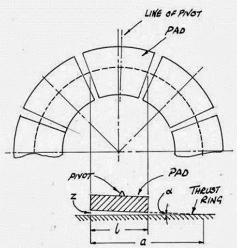
  • In propulsion machinery, the thrust bearing most commonly used is tilting-pad type.
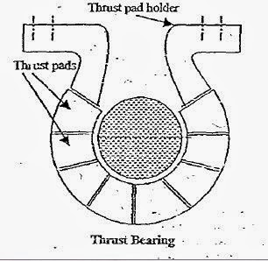
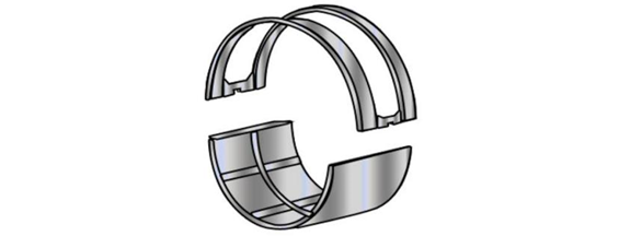
  • In tilting pad type of bearing a thrust collar is forged integrally with the thrust shaft. on the forward and aft side of the thrust collar, the thrust pads are fitted.
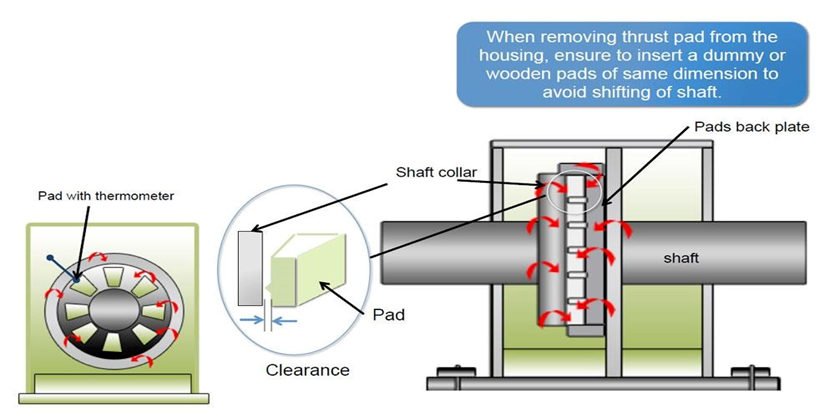
  • The thrust pads are lined with white metal and face on to the finally machined and polished surface of the thrust collar. The back of the pad has a radial ridge, which forms a fulcrum on which the pad can tilt. The tilting fulcrum on the back of the pad comes in contact with a solidly constructed housing. The housing is rigidly held in the thrust bearing casing.
  • this type of bearing builds up an oil pressure between the white metal face of the thrust pad and the thrust collar when the shaft revolves. The oil pressure is due to the formation of an oil wedge, which can build up only when the thrust collar is supplied with the oil and is revolving. As the pad is able to tilt it becomes self-adjusting to the shape of the wedge.
  • The thrust acting on the thrust collar is balanced by the oil pressure created by the tilting pad and thus transmitting the thrust to ship hull via tilting pad and housing.
  • The radial ridge on the back of the pad, which becomes the fulcrum for the tilting action is often made off center. If the thrust pads are viewed from the top, the tilting point is always from the center moving in the direction of rotation of the collar.

Bottom end bolt:

.bottom end bolt .bebf   .cpbf   .crank pin bolt .crbf .connecting rod bolt failure

.con rod bolt .bolt failure

a) Causes of bottom end bolt failures:

»          Stress concentration in way of change of section, damaged fillet, damaged surface finish

»          Over stretching / tightening causing permanent damage due to plastic deformation

»          Uneven tightening causing overloading of some bolt

»          Inadequate pretension causing high fluctuation of stress in bolts and consequently fatigue failure.

»          Improper seating of bolt head and nut resulting in bending stress in bolts

»          Corrosive attack due to contaminated lube oil.

a)       Methods used to tighten the bottom end bolts

.bebt   .cpbt .crbt

Hydraulic cylinder & followed up nut:

»          During tightening, measurements of extension are essential for correct strength.

»          All hydraulic equipment to be checked & calibrate the pressure gauge.

»          Tightening must be done more than one stage.

»          Final tightening pressure must not be applied at a time.

»          Tightening to be done in sequence as per maker’s requirement.

»          Tightening must be done in following sequences.

0 0 STBD                                 O 2

0 0 PORT                                 0 1

Fig: For 4 bolts            Fig: For 1 bolt.

Torque spanner:

»          First do calibration of torque spanner & adjust the set torque.

»          Torque should be applied in more than one stage.

»          During final torque applied all work must be done by one person & slowly.

Hand tightening:

»          Place one mark on bolt head.

»          Place two mark according to angle of final tightening as per maker‘s instruction

»          Do that in more than one stages.

In all three types of tightening, it has to be made same. ensure bolts have reached their reference mark on

connecting rod reference mark. Angular accuracy is essential for correct tightening load.

c. Modern design of bottom end bolts:

»          Shank diameter is 10% less than core diameter

»          Fillet is provided between shank and bolt head to prevent stress concentration

»          3 to 4 threads remain free below contact face of the nut

»          High degree of surface finish to prevent stress concentration

»          Cold rolling of threads to improve fatigue strength

»          Bolt stiffness to be less than bearing housing – less dynamic load on bolt

»          High UTS alloy steel with long thin elastic bolts for higher fatigue strength

»          Fitted portion to keep as short as possible to prevent stress concentration and to obtain greatest resilience

d) Inspection and maintenance of bottom end bolts:

»          Sound testing to detect internal flaws and cracks

»          Bolt threads

»          Surface finish of bolts

»          Fillet area

»          Cracks

»          Measuring elongation of bolts

»          Checking pretension of bolts

»          Checking locking device if any

Crankshaft

.crankshaft failure

Factors contributing to failure on a crankshaft

Cracks

  • Different parts of crankshaft are subjected to different kinds of stresses.
  • Cracks weakens crankshaft areas thus leads to failure.

Crankshaft corrosion attack

  • Decomposition and oxidation of oil in service
  • Contamination of lubrication oil by fuel oil
  • Contamination of lube oil by acidic products of combustion (4 stroke engine)
  • Possibility of stray electric current entering crankcase resulting electro chemical corrosion
  • Oil carrying air bubble with it causes pitting corrosion

Crankshaft twisting or slipping

  1. If an attempt is made to start the engine when:
    1. Turning gear is engaged
    1. Water or fuel accumulation on piston crown.
    1. Propeller is confined by ice log
  2. During operation propeller strikes with submerged object
  3. Seizure of engine component.
  4. Bottom end bolts failure.
  5. Crash astern movement.

Misalignment of crankshaft

  1. Main bearing damaged
  2. Defective propeller shaft bearing
  3. Slack or broken tie bolts
  4. Foundation bolts loosen or fracture
  5. Engine chocks broken, cracked, or fretted
  6. Bedplate deformed / damaged
  7. Hull deformation due to Grounding; Fire
  8. Weakening of structure due to corrosion

Checking crankshaft deflection/alignment

.crankshaft deflection .deflection .cd  .csd

We take crankshaft deflection to make sure that the crank runs and maintain proper balance

Preparation 

  • Take immobilization permission
  • Block starting air valve and put sign
  • Propeller clearance
  • Tool box meeting
  • Risk assessment and work permit done
  • Enclosed space entry permit done
  • Open crankcase door and ventilate and then check with oxygen analyzer
  • Weather is calm
  • No operation of loading discharging
  • Ship not in drydock
  • No maintenance on other engine part

Procedure

Deflections results interpretation

Vertical deflection:

  • Difference between top and bottom clearance is the vertical deflection

Horizontal Deflection

  • Difference between port and starboard side clearance is the horizontal deflection.
  • This value is usually very low.

 Accuracy checking of deflection reading

The values of T+B and P+S should nearly the same. Otherwise, the measurement need to be repeated for the unit.

SOLAS Reg. for c/c Relief v/v

  • SOLAS Chap II-1, Part C – Machinery Installations, Regulation 27, Item 4
    • Internal combustion engines of a cylinder diameter of 200 mm or a crankcase volume of 0.6 m3 and above shall be provided with crankcase relief valves of a suitable type with sufficient relief area.
  • SOLAS Chap II-1, Part E – UMS Regulations, Regulation 47, item 2
    • Internal combustion engines of 2,250 kW and above or having cylinders of 300 mm bore shall be provided with oil mist detectors.
  • Larger engines (>300 mm cylinder diameter) require one relief valve on each crankcase door
  • Smaller engines (≤300 mm cylinder diameter) may have relief valves at the crankcase ends
  • The combined free area of valves must be at least 115 cm2/m3 of crankcase gross volume
  • Minimum free area should not be smaller than 45 cm2.
  •  

Crankcase Relief Valve Installation and Placement

The number and placement of relief valves depend on engine size:

→ Engines with cylinders 200-250 mm bore: At least two valves, located at or near crankcase ends.

→ Engines with cylinders 250-300 mm bore: One valve per alternate crank throw, minimum of two valves.

→ Engines with cylinders >300 mm bore: One valve per main crank throw.

Crankcase Relief Valve Maintenance and Safety:

Key maintenance points include:

→ Regular inspection for leaks during engine operation

→ Replacement of O-rings if leaks occur

→ Visual inspection of flame arresters after any work that could cause mechanical damage

→ Complete replacement of flame arresters after a crankcase explosion

 Inspection:

State the procedure for crankcase inspection

.crankcase inspection .cc inspection

Purpose:

To look for early sign of failure

Preparation:

· Tool box meeting carried out.
· Carry out proper risk assessment and work permit taken
· Enclosed space entry permit to be taken and enclosed space entry procedure to be followed
· Inform bridge and put warning notice at ECR
· Block the starting mechanism and stop L.O pump
· Open indicator cocks and engage turning gear
· Propeller clearance taken
· Turning gear must be operated by only in remote mode
· All personnel involved should not have any object in their pocket
· Instrument/tools to be used should be checked and counted

Procedure:

Starting from the top
1. Check stuffing box arrangement
· Ensure locking wires and bolts are intact
· Check drainpipe is clear
2. Check crosshead bearing for any sign of wiping
3. Check cross guide shoes for any abnormal sign of scoring
4. Check lube oil telescopic pipe for any sign of leakage due to loosen connection
5. Check bottom end bearing bolts and nuts for any slackness and sign of wiping
7. Check crank web and journal of crankshaft (semi-built type) for any sign of slippage comparing to the reference mark provided
8. Check main bearing bolts for slackness and sign of wiping
9. Check tie rods for slackness
10. Check transverse girder for any cracks if any doubt carry out die penetrant Check
11. OMD sampling cup for blockage
12. Check crankcase relief valve gauge for dents, wetness, and form of clogging

13. Check crankcase floor and drain traps for any metallic debris present
14. Close all unit crankcase door and start lo pump
· One at a time open the crankcase door to inspect the oil flow pattern comparing to the other unit. Flow pattern will differ when there is a reduction of LO flow or early sign of bearing failure
· Check crosshead lube oil piping linkage for leakages if possible
· For chain gear compartment check the oil spray nozzle for any change in oil flow and the condition of rubber guide and clearance.
· For chain thrust bearing check oil nozzle for clogging and flow pattern

Crankcase

.crankcase explosion .crank case explosion .cce

Causes leading to crankcase explosion

The causes of crank case explosion is the hot spot.

Sources of hot spot:

1. bearings:

·Main bearings.
· Bottom end bearings.
· Crosshead- bearings, guide shoes/slides.
· Gudgeon pin bearings. (4 stroke)
· Transmission gear/ chain gear.

2. Piston crown crack
3. Hot piston.
4. Hot gases blow past.
5. Scavenge fire.

Source of fuel:

· Lubricating oil vapor.
· Lubricating oil contaminated by fuel vapor.
· Leaky fuel injector causing semi-burnt fuel to enter crankcase.
· Piston crown crack

a. primary explosion:

  1. The cause of crank case explosion is the hot spot.
  2. under normal running condition air in the crankcase will contain oil droplets by system oil splashing.
  3. If hot spots exist, some oil will encounter it and will be vaporized,
  4. This vaporized oil circulates to cooler region of crankcase and condense to form white mist.
  5. this white mist is combustible at certain concentration.
  6. If this mist is circulated back to the hot spot with this concentration, it will be ignited, and primary explosion will take place.

Secondary Explosion:

  1. After primary explosion sufficient pressure and shock wave will build to rupture the crankcase door unless it is released by c/c relief valve.
  2. In this event low pressure wave will draw air back into the crankcase where it will mix with vaporized and burning oil to create secondary explosion.

How to prevent:

  •  Avoid hot spot by proper engine maintenance & operation.
  • Avoid fuel contamination and overheating of lube oil
  •  Detect vapor generation at early stage by oil mist detectors.
  • Maintain Crankcase relief door properly to prevent secondary explosion.

Warning and prevention devices:
· Oil mist detector: Range 0-10% LEL, Alarm 5% LEL (2.5 mg/L).
· Crankcase pressure relief door: opening pressure 0.2 bar maximum.

Action/ standing order in the event of OMD alarm:

  1. Upon OMD alarm additional generator should started & take on load
  2. Do not check or reset the OMD locally
  3. Engine will auto-slow down
  4. Inform bridge to stop engine
  5. All personnel leave engine room immediately
  6. Enter engine room only after engine has come to a complete stop or after30 minutes whichever is longer.
  7. Do not stop the LO pump
  8. Open the indicator cock
  9. Approach to turning gear should be away from the crankcase doors with relief valves
  10. Turn the engines for 30 minutes

Engine should be sufficiently cooled before crankcase doors are opened for inspection

Oil mist detector

Fitting of Oil Mist Detector gives early warning & slowdown, hence reduce the intensity.

 consist of –

1. Infra- red light source transmitter 

2. Compensating receiver 

3. Measuring receiver

Operation:

  1. when infra-red light source start transmitting, some lights are directly received by compensating receiver and rest lights are being scatter by oil particles received by measuring receiver
  2. Compensating receiver situated directly opposite to the transmitter, which measures the amount of contamination building upon the transmitter.
  3. Measuring receiver is install 90 degrees to the transmitter. The amount of scattered light received by measuring receiver almost linearly indicates mist concentration in the crankcase.

If your oil mist detector breaks down, how would you safely continue operating your main engine?

  • Engine room must be manned (no UMS)
  • Using laser to measure crankcase door temperature
  • Check temperature of breather pipe
  • Fumes being emitted through the breather pipe at funnel oil mist box
  • High lub oil bearing temperatures
  • Higher piston cooling oil temperatures
  • High thrust bearing temperature
  • Chain case compartment temperature

Crankcase relief valve

.crankcase relief valve .cc valve .c/c valve

Purpose and Function

Crankcase relief valves serve two critical functions:

  1. Relieve excess pressure inside the crankcase to normalize internal pressure
  2. Prevent flames from escaping the crankcase in case of an explosion

These valves are essential safety devices designed to mitigate the risks associated with crankcase explosions, which can have severe consequences including injury to personnel and extensive engine damage.

Design and Operation

Crankcase relief valves are:

  • Lightweight, spring-loaded, self-closing devices
  • Designed to open quickly at a pressure not exceeding 0.02 N/mm2 (0.2 bar)
  • Constructed with valve discs made of ductile material to withstand shock.

The valves operate by:

  • Opening rapidly when internal crankcase pressure increases between 0.2-1.0 bar
  • Closing positively and rapidly after pressure is relieved
  • Preventing the ingress of fresh air (non-return functionality

Soot fire:

.soot fire  .sf

b) Indication of soot fire:

  1. Sudden rise of economizer outlet temperature during normal operation.
  2. Economizer outlet temperature remains high despite main engine speed reduction.
  3. Smoky funnel
  4. Spark emission from the funnel
  5. Sudden rise in steam pressure

c) Soot:

Comprises of ‘unburnable’ components in the fuel oil:

  1. Ash
  2. Carbon Residue
  3. Vanadium
  4. Products of improper combustion
  5. Excessive Cylinder Lubrication

Factor of soot fire:

  • Low Quality Residual Fuels
  • Prolonged low load operation
  • Low Gas Velocity
  • Main engine not efficiently operated
  • products of improper combustion
  • Excessive cylinder lubrication
  • Improper boiler water treatment
  • Irregular EGE cleaning.
  • Irregular soot blowing

Prevention of EGE/EGB fire/Soot fire:

  1. Bunkers meet engine specification   
  2. Purification of fuel  
  3. Avoid running the at low load condition.  
  4. Good combustion of ME
  5. Maintain correct cylinder lubrication
  6. Proper boiler water treatment
  7. Regular soot blow
  8. Regular EGE cleaning.
  9. Regular monitoring of temperature and pressure differential across tube stack

d) Necessary actions for soot /EGE fire:

  1. Immediate action is to slow down M/E
  2. Stop M/E if fire is confirmed as M/E exhaust gases contain > 17% oxygen
  3. Stop auxiliary blowers.
  4. seal turbochargers air inlets
  5. Keep EGE casing closed from ingress of air or gases
  6. Keep boiler water circulating p/p running during fire.
  7. Boundary cooling

e) EGE dry running: 

    .ege dry   .egedr

    1. Permitted during emergency only. 
    2. EGE coils should be free of soot accumulation
    3. Inlet & outlet v/v fully closed & vent or drain v/v’s fully open. 
    4. No ingress of water into tubes. 
    5. Refer to manufacturer’s instruction manual M/E load maybe restricted
    6. Exhaust gas temp at inlet of EGE may have restriction (<350deg)
    7. Soot blowing operation may not be allowed
    8. But if there is prolonged low-load operation of main engine operation, then frequent soot blowing operation may be required
    9. After repairs, water washing must be carried out before re using EGE

    Scavenge Fire:

    .scavenge fire   .sf  .scav fire

    Various factors can cause scavenge fire. These are:

    CAUSES OF SCAVENGE FIRE:

    1. Blow past due to damaged piston ring profile and liner
    2. Poor combustion due leaky fuel injector, faulty fuel pump timing
    3. Leaky or improper timing of exhaust valve.
    4. Wrongly timed or excessive cylinder lubrication
    5. Stuffing box leak bringing system oil into scavenge space
    6. Buildup of deposits due to clogged scavenge space drain by:
      1. Cylinder oilUn-burnt fuel
      1. Crankcase oil(if the stuffing box scrapper ring is fitted in wrong way)

    b) Symptoms/indication:

    Indications of scavenge fire are:

    1. Increased exhaust temperature of affected cylinder
    2. Affected unit under piston temperature high.
    3. Spark emits from scavenge drain
    4. Scavenge manifold noticeably hotter
    5. Turbo charger may surge
    6. Smoke from t/c air inlet filters when surging
    7. Thick black smoke emitted at funnel
    8. Engine slow down due to reduced power.

    c) Action to be taken:

    As EOW:

    1. Immediately inform bridge and slow down main engine to ‘Dead Slow’
    2. Activate Engineers’ Call Alarm
    3. Shut scavenge manifold drain valve & leave vicinity

    chief engineer will:

    1. Request bridge for permission to stop
    2. Stop engine when order received
    3. Stop auxiliary blowers
    4. Seal t/c air filters with canvas
    5. Stop fuel oil supply to engine
    6. Put the scavenge manifold fire extinguishing system into operation to extinguish the fire.
    7. Open indicator cock, engage turning gear and turn engine to prevent seizure
    8. Lube oil pump must be running

     Inspection Criteria after extinguishing fire:

    1. After fire, remove dry deposits and sludge from scavenge space
    2. Check scavenge drain pipes if clear
    3. Clean and inspect the piston rods, stuffing boxes and cylinder liners.
    4. Check piston and rings condition
    5. Check tightness of tie rods
    6. Check aux blowers non-return flaps
    7. Check air cooler condition by opening the air side drain valve for possible CW leakage while cooling water is being supplied.

    Prevention:

    To prevent scavenge fire

    1. Fuel injection equipment need to be maintained in good condition and correct injection timing
    2. Maintain Piston rings in good condition and liner wear within limit
    3. Maintain Cylinder oil feed rate within limits
    4. Stuffing box sealing rings and scraper rings maintain in good condition
    5. Keep Scavenge ports clean
    6. Clean scavenge trunking and drains regularly.
    7. Never use flammable materials that may vaporize, such as gas oil or kerosene, to clean inside the scavenging space.

    Fire but main engine cannot be stopped:

    In the event of the scavenge fire occurring and that the main engine cannot be stopped, then the following course of action would be taken:

    1. Contact the Bridge and request to slow down to the lowest power possible
    2. Increase the cylinder lube oil feed rate to the affected cylinder
    3. Lift the fuel pump on the affected cylinder (cut off fuel), using the manual activation of the air cylinder (option fitted for fuel pipe leakage system).
    4. Prepare the firefighting equipment to tackle any fire that may be emitted from the scavenge receiver relief valve.
    5. Move all personnel away from the engine, should the scavenge fire burn long enough to trigger a crankcase explosion.
    6. The scavenge fire should burn out, once all the oil is consumed.
    7. Stop the engine as soon as possible, to allow the fire (if still burning to be extinguished) and the affected areas within the engine to be inspected.

    Draw and explain starting air valve

    .sav   .starting air valve .sa line

    Materials

    The body of the valve could be of mild steel, the spindle of high tensile or stainless steel, and the valve and seat could have the contact faces stellite or hardened.

     Stellite 

    It is a range of cobalt-chromium alloys designed for wear resistance. The alloys may also contain tungsten or molybdenum and a small, but important, amount of carbon. Also used as cutting tool.

    Starting air line safety:

    .starting air line safety .starting air safety .sa safety .sa line safety

    Different safety devices are installed on starting air line, in order to prevent explosion.

    Bursting Disc   It is installed on starting air pipe, between the manifold and the air starting valve. It consists of a  perforated disc made of a sheet of materials which will burst in case of excessive pressure secondary to an explosion. Bursting disc is designed in such a way that engine will run even after the disc get ruptured, there is a protective cap on the bursting disc which will cover the hole.

    Flame Arrestor   Flame arrestor helps to arrest any flame coming out of the cylinder through leaking start air valve.

    Relief valve    It is affixed on common manifold which shall lift and relieve excess pressure inside the manifold.

    Non Return Valve    It will not allow the return of any gas from the manifold to the air receiver.

    Starting Air SOLAS Requirement:

    .starting air regulation .sa regulation

    1. For first start arrangement: arrangement for air starting is to be provided so that necessary air for the first charge can be produced onboard without external aid / emergency compressor.

    2. For air compressor requirement:

    i) Must be fitted with two or more air compressor.

    ii) Total capacity of air compressor is to be capable of charging the air receivers within one hour from  atmospheric pressure

    iii) At least one of the compressors driven independent of main propulsion unit, which acts as emergency air compressor

    iv) Capacity not less than 50% of total requirement or approximately divided between them

    3. Maximum discharge air temperature: discharge temperature not substantially exceed 930c in service.

    4. Air receiver requirements:

    i) Two equal capacity of air receiver are provided.

    ii) Total air receiver capacity is to be sufficient to provide without replenishment:

    → For reversible engine: not less than 12 consecutive starts of M/E altering between ahead and astern

    →  For non-reversible engine not less than 6 consecutive start of M/E in pitch propeller.

    Causes of starting air explosion

    .sa explosion     .sale .sae .airline explosion .air line explosion

    .starting air explosion

    • The main cause of starting airline explosion is leaking or sticking/sluggish/erratic operation of the cylinder starting air valve.  Due to the this the hot semi-burned fuel gets forced into the starting air manifold. This is because firing pressures are generally higher than 100 bars as compared to starting air pressures of 30 bar.  As more of the hot semi-burned fuel accumulates in the air line, the fuel reaches the explosive limit and spontaneously ignites causing an explosion.
    • Also the oil which is discharged from the air compressor to starting airline system. It will deposit as a thin moist film on the internal surface of the pipes but not ready to combustion. If starting air valve leaky hot gas or flame may enter the starting air manifold, and cause starting airline explosion

    Indications of an imminent starting air line explosion?

    1. The starting airline manifold starts to
    2. Becomes ‘smoky’ due to paint burning
    3. Blisters’ or ‘bubbles’ form on painted manifolds
    4. The manifold becomes glowing red hot
    5. Due to loss of compression pressure, unit may experience high exhaust temperature and power developed will be lower

    How to prevent starting air line explosion?

    1. maintain air start valves
    2. maintain starting air lines clean
    3. drain air bottles regularly
    4. maintain compressor lubrication
    5. open air line valves slowly

    How do you check the cylinder starting air valve for leak?

    1. Finished with engine
    2. Get propeller clearance from bridge
    3. Indicator cocks must be open
    4. Unit to be tested to be brought to TDC
    5. Turning gear must be disengaged for test
    6. Control air to starting air distributor must be SHUT
    7. Automatic starting air valve must be manually opened
    8. If start air valve leak, loud hissing sound is heard at indicator valve.

    If turning gear is engaged and for some reason the engine turns, the whole turning gear assembly can get ripped off its foundation.

    What protective/safety devices are fitted to overcome starting air line explosions.

    1. Relief valve
    2. bursting disc
    3. flame trap
    4. Non return valve

    Studies have shown that most occurrences of starting air line explosions took place during manoeuvring than at sea, why?

    1. Because only during manoeuvring we operate the starting air valve so during this time the possibility of sticking or sluggish operation of the v/v is high.
    2. Also during the manoeuvring air is present in the manifold where at sea there is no air in the manifold.

    Types of lubrication:

    Hydrodynamic Lubrication:

    Cont oil film due to moving surfaces. Film due to motion of the moving parts. Journal bearing

    Hydrostatic Lubrication:

    Oil film doesn’t form naturally but pressure needs to be applied externally. Crosshead bearing

    Boundary Lubrication:

    Thin film between closely met surfaces. Contact might have been there.

    Electrohydrodynamic lubrication:

    Oil wedge thickness changes due to elastic deformation of the mating surfaces. Between gears

    1. *Boundary Lubrication*:

       – This occurs when a thin layer of lubricant is present between two surfaces, preventing direct metal-to-metal contact. It is common in conditions where full fluid lubrication is not achievable, such as during start-up or shutdown.

    2. *Hydrodynamic Lubrication*:

       – In this type, a full film of lubricant separates the moving surfaces completely. This film is maintained by the movement of the surfaces, creating a pressure that supports the load. It is typical in high-speed rotating machinery like main engines and shaft bearings.

    3. *Electrohydrodynamic Lubrication*:

       – This lubrication occurs in rolling contacts, such as those found in ball and roller bearings. The lubricant film is thin, but due to the elastic deformation of the surfaces, it can still carry high loads.

    4. *Mixed Lubrication*:

       – This is a combination of boundary and hydrodynamic lubrication, where both thin and thick films of lubricant coexist. It usually occurs during the transition between boundary and hydrodynamic lubrication phases.

    5. *Grease Lubrication*:

       – Grease is used where oil lubrication is impractical or where the machinery is exposed to the elements and contamination. It is commonly used in bearings, seals, and other components that require infrequent lubrication.

    6. *Oil Mist Lubrication*:

       – This method involves dispersing a fine mist of oil into the air, which then lubricates the machinery as it condenses on the surfaces. It is often used for high-speed or high-temperature applications where traditional lubrication methods might fail.

    7. *Splash Lubrication*:

       – In this system, parts of the machinery splash oil from a reservoir onto moving components. It is commonly used in small engines and gearboxes.

    8. *Forced Lubrication*:

       – Oil is pumped under pressure to critical parts of the machinery to ensure consistent lubrication. This type is typically used in large engines and complex machinery where reliable lubrication is crucial.

    Ball Bearing and Roller Bearing:

    .ball bearing .roller bearing

    Ball bearing have single contact on it rolling race. Friction is less, heat generation is less. Designed for low load application. Thus grease lubrication is enough.

    Roller bearing contact point is an entire line, friction is more, generates more heat. Designed for larger load. So it needs extra lubrication.

    Bearing types and material:

    1. Tin based white metal – Thin or Thick metal

    Alloy of 88% Tin(Sn), Antimony(Sb), Copper(Cu), Cadmium

    2. Thin shell– 40% Tin Aluminium (Al Sn 40)

    Dynamic loading capacity is higher.

    Overlayer – Thin layer of Lead (Pb) and Tin (Sn) [for surface conformity embed]

    Used for crosshead bearing

    3. Flash layer – 100% Tin (Sn)

    Corrosion protection (oxidation)

    Works on any dry – lubricant

    4. Thin shell (have nip crush) – 2-2.5% of journal diameter

    Thick shell – 30-60 mm

    → used only for main bearing

    Crosshead bearing lower shell made of Tri-metal, steel back, white metal, overlayer

    Upper shell – Bimetal – No overlayer

    Both have flash layer

    Bearing Nip crush:

    It provides a compressive force to the bearing shells resulting in what I would call an interference fit, if it were a one piece cylindrical bearing pressed into a bore. The object is to keep the bearing shells in place without having them spin inside the bore, or work their way out the end of the bore while a rotating shaft is spinning inside.

    1.  

    Broken Roller Bearing in Auxiliary Engine:

    Broken Roller Bearing in AE

    A broken roller bearing in an AE (Air Eliminator) fuel pump can lead to various issues. Here are some common causes and recommended actions:

    Causes

    • Lack of Lubrication: Insufficient lubrication can lead to excessive friction, causing the bearing to overheat and eventually break.
    • Contamination: Dirt, debris, or other contaminants in the fuel or lubricant can damage the bearing surfaces.
    • Misalignment: Incorrect alignment of the pump components can put uneven stress on the bearings, leading to premature failure.
    • Overloading: Operating the pump beyond its designed capacity can exert excessive forces on the bearings.
    • Wear and Tear: Bearings have a finite lifespan and can break down due to normal wear and tear over time.
    • Improper Installation: Incorrect installation procedures, such as using the wrong tools or applying improper techniques, can damage the bearing.

    Actions

    • Inspection and Replacement: Inspect the damaged bearing and replace it with a new one. Ensure that the replacement bearing is compatible with the pump specifications.
    • Lubrication: Ensure proper lubrication of the new bearing and check the lubricant quality and quantity regularly.
    • Contamination Control: Implement filtration systems to prevent contaminants from entering the fuel pump system. Regularly check and replace filters.
    • Alignment Check: Check alignment of the pump assembly.

    Crosshead bearing

    The crosshead bearing design in latest engines depends on the pressure of the lube oil supplied to them.

    In MAN engine, the crosshead lube oil pressure is same as that of main lube oil system. This is due to the design of the lower shell of the crosshead bearing which has machined wedges to hold oil in them and to support the hydrodynamic lubrication of crosshead pin.

    The top shell consists of a cut out part where the piston palm passes and connected to the crosshead pin.

    In MAN engine, the lube oil is supplied to the crosshead from telescopic pipe, which is attached to the crosshead face.

    IN SULZER engine, the old type model comprises of forked crosshead i.e. the piston rod passes right through the crosshead and is secured underneath with means of piston nut. The crosshead bearing has machined grooves to support oil and lubrication.

    In latest SULZER engine, only the lower shell is present which is continuous in nature and the upper bearing housing is lined with white metal.

    The oil pressure for crosshead is maintained at 10-12 bar by means of separate crosshead booster pump, which increases the main lube oil pressure.

    Material

    In MAN engine, the lower shell with grooves is made from SnAL40 and the upper shell is of white metal. While in SULZER, the bearing shell is thin walled made of white metal for high load bearing capacity.

    Bearing Survey:

    • As a Chief Engineer how would you inspect a bearing that is being prepared for survey?

    inspection and survey of a bearing

    .bearing survey   .bs    .mebs    .mbs

    Prior to Opening Bearing for Repair/ Survey:

    • Take immobilization permission from port authority
    • Enclosed space entry permit must be taken
    • Perform tool box and risk assessment of the job
    • Ensure to check the previous bearing opening/ survey report
    • Check details of the records and clearances
    • Check shore lube oil analysis record
    • Check work done report or log book for any important points on the bearings (grinding or pin/ under or oversize bearing etc.)
    • Check all the photographs of the last opened bearing
    • Check all bearing related service letters from the manufacturer
    • Perform onboard lube oil test and note down the results

    Safety check for main engine:

    Before undertaking any work on the engine, the following safety checked should be carried out: 

    1. Permission granted to immobilize engine.
    2. Risk assessment should be carried out.
    3. Work permit to be taken.
    4. Starting air shut off and locked off. 
    5. Open the indicator cock.
    6. Engine cooled down sufficiently to allow L.O pump to be shut down.
    7. Check that no one is working on the vicinity of the shafting. 
    8. Take propeller clearance from bridge.
    9. All lifting gear, shackles etc checked for defects and check they are within certification.

    Tool box meeting should be carried out, only the person in charge of operation is to operate the T/G.

    Bearing Inspection

    .bearing inspection

    1.  Dis-coloration
    2. Estimate percentage of discoloration
    3. Signs of overheating
    4. Lacquer formation
    5. Removal of overlay
    6. Microbial attack
      1. Scoring
    7. Due to impurities/abrasive particles in the lub oil
    8. Bearing wear particles
      1.  Pitting marks
    9. Foaming of the lub oil
    10. Spark erosion due to earthing problem (mainly on thrust & main bearings and journals)
      1.  Flaking
    11. Ageing, water in lub oil
      1. Signs of Fretting due to
    12. Incorrect tightening
    13. Applying oil/grease at the back of bearing shells before assembly
      1. Wear down

    – Measure the thickness of the bearings

    • Cracks
    • overloading
    • Use dye penetrant check
      • Oil Grooves
    • Enlargement of grooves due to erosion/corrosion
      • Oil holes

    – enlargement/blockage

    1. Dowel pin/holes if fitted

    – slackness

     Replacement of bearings to be done as per maker’s instruction. For e.g., if overlay alloy is wiped out or oil wedge in the bearing is reduced in dimension etc.

    Journal / Pin 

    • discoloration
    • Roughness
    • Hardness check
    • Surface finish
    • Diameter/ovality check
    • Crack detection
    • Oil holes check

    If scoring, pitting, cracks etc. exist in the pin, same to be polished, grinded, or reconditioned

    • The pin and the bearing to be thoroughly cleaned and lube oil to be put before fitting
    • Take enough photographs while doing the maintenance or survey

    After Repair/Survey:

    – Ensure the bearing and other parts are secured as per manual instructions
    – The tightening value of the hydraulic bolts to be crosschecked and it is to be done in the presence of senior engineer officer
    – Engine to be turned by turning gear for at least 10 minutes with lube oil pump on and oil pressure recorded
    – The turning gear current to be observed during this process
    – Once the engine is closed and ready, running-in to be performed as per makers instructions
    Record all the parameters
    – Prepare the maintenance/ survey report
    File the report in ship’s record and send the complete work with photo proof to the office. This can be used as a reference during continuous machinery survey and the concerned bearing need not to be opened.

    Main Engine Safety Devices, Alarms, Trips and Shut Down:

    Main engine safety systems are critical for protecting the engine and ensuring safe operation of ships. They typically include:

    Safety Devices

    • Crankcase relief doors
    • Scavenge space relief doors
    • Cylinder head relief valves
    • Starting air relief valves
    • Oil mist detectors
    • Overspeed trip devices

    Alarms

    • Low lube oil pressure
    • High cooling water temperature
    • High exhaust gas temperature
    • Low fuel pressure
    • High oil mist concentration

    Trips and Shutdowns

    Trips and shutdowns automatically stop the engine in dangerous conditions:

    • Very low lube oil pressure (< 1 bar)
    • Very high jacket water temperature (> 95°C)
    • Overspeed (typically 107% of max continuous rating)
    • Oil mist detector activation
    • Manual emergency shutdown

    Interlocks:

    Interlocks prevent starting the engine in unsafe conditions:

    • Turning gear engaged
    • Wrong running direction
    • Low starting air pressure

    Crosshead bearing failure:

    .crosshead bearing failure .cross head bearing .chbf .ch bearing .c/h bearing  

    Crosshead bearing failure:

    .cross head bearing failure   .chbf   .cbf

    Possible causes/ Possible defects of cross head bearing failure are: 

    1. Fatigue failure

         Due to reuse of old spare, ageing, unavailability of spare crosshead pin – hand polished spare used. 

    • Reduced lube oil flow

     Due to oil leakages at pipe connection (chock oil passage).  

    Excessive clearance due to wear down of pin. 

    • Excessive firing load

     Due to improper power balancing. 

     Early firing due to early injection.

    • Misalignment

     Due to uneven wear down of guide shoe & crosshead pins.  Piston rod bent, excessive liner wear. 

    • Crosshead pin may have high hardness

     Due to wear down/ scoring over prolonged time.  

    • Oil groves in bearing enlarged:

            Due to erosion/corrosion. 

    • Slack tie bolts/ inadequate tightening.
      • Improper tightness of crosshead bearings nuts.

    Minimizing crosshead bearing defect:

    How to minimize /prevent: 

    1. Oil in circulation is of correct quantity. – 15-18 times per hour circulation. (For 2 stroke engine LO= pump capacity/15) 
    2. Purification is constantly carried out. 
    3. Ensure oil topped up at regular intervals, of not more than 10% of sump volume.
    4. Oil testing and appropriate remedial action taken. 
    5. Carry out regular crankcase inspection
    6. Check for crosshead oil leakage at cross head pipe hinges and oil flow pattern. 
    7. Regular clearance check between guide shoes & pins.
    8. Crosshead bearing clearance check
    9. Take M/E performance data & power balancing.

    Action as CE in case of crosshead bearing failure:

    As a Chief Engineer facing a crosshead bearing failure at sea, CE should take the following actions:

    1. Stop the main engine immediately to prevent further damage.

    2. Inform the bridge and the company about the situation.

    3. Obtain permission for immobilization from the port authority if near coastal waters.

    4. Ventilate the crankcase properly and ensure all personnel wear appropriate PPE before entering.

    5. Inspect the damaged bearing to identify the cause of failure. Look for signs of:

       – Scoring, pitting, or cracking on the bearing surface.

       – Wiped out overlay alloy

       – Reduced oil wedge dimensions.

       – Water contamination in the lube oil system

    6. Check the crosshead pin for cracks using Non-Destructive Testing (NDT) methods.

    7. Examine the crosshead guides and guide bearings for any defects.

    8. If possible, dress up minor damages on the bearing as per manufacturer instructions.

    9. Replace the damaged bearing with a spare if available. Ensure the new bearing is installed correctly following maker’s guidelines.

    10. Clean the pin and bearing thoroughly before reassembly.

    11. Record all clearances and compare with maker’s tolerances.

    12. Ensure proper tightening of all bolts and fasteners.

    13. Run the lube oil pump and turn the engine on turning gear to check for proper oil flow and unrestricted movement.

    14. Perform a running-in procedure as per the maker’s instructions if a new bearing is installed.

    15. Monitor engine parameters closely during initial operation after repair.

    16. Prepare a detailed report of the incident, including photos, for company records and classification society.

    17. Review and implement preventive measures to avoid future failures, such as:

        – Regular oil analysis and purification.

        – Proper alignment checks.

        – Scheduled bearing inspections.

        – Monitoring engine performance and power balance.

    Thrust Bearing

    When the crank throw is loaded by the gas pressure through the connecting rod mechanism, the arms of the crank throw deflect in the axial direction of the crankshaft, generating axial vibrations.

    These vibrations may be transferred to the ship’s hull through the thrust bearing. The thrust bearing is incorporated in the aft end of the bedplate as differential expansion of the shaft and hull is minimum at the aft due to fuel heating in tanks.

    The aft-most cross girder is therefore designed with ample stiffness to transmit the variable thrust from the thrust collar to the engine seating.

    It is advised to align the thrust bearing when main bearing alignment is carried out to achieve accuracy.

    Material

    Michell type pads bearing arrangement consists of a steel forged thrust shaft, a bearing support, and segments of cast iron with white metal.

    The thrust shaft is connected to the crankshaft and the intermediate shaft with fitted bolts. The thrust shaft has a collar for transfer of the ‘thrust’ through the segments to the bedplate.

    Lubrication of the thrust bearing takes place from the system oil of the engine. At the bottom of the bearing there is an oil sump with an outlet to the oil pan.

    Clearance

    The clearance in the thrust bearing is measured during test bed trials of the engine.

    For a new engine the clearance is 0.5-1.0 mm, and for an engine in service it must not exceed 2.0 mm.

    Dismount the foremost segment stopper On top of the thrust segment, a wear groove of 1mm is provided (a segment with thermometer). To measure the wear, push the thrust pad with crowbar against thrust cam to eliminate any gap at the back

    While Inserting feeler gauge in the groove, if 0.1 mm is not able to enter, it indicates wear is more then 0.9 mm and the bearings need to be overhauled.

    If the white metal is found scored, fine scrapping can be done to wipe off the scoring marks. The liner shims can be inserted at the back of the thrust shoes to make the clearance of all thrust pads equal. This avoids uneven loading of pads

    Crankpin bearing Clearance:

    .crank pin bearing clearence   .cpbc    .bebc    .bbc

    Turn the concerned crank to BDC

    Measure the clearance in the crankpin bearing by inserting a feeler gauge at the bottom of the bearing shell on both sides

    The wear limit for the crankpin bearing shells is based on an evaluation of the bearing condition at the time of inspection. An average wear rate of 0.01 mm per 10,000 hours is regarded as normal

    In modern shell bearings, the clearance is manufactured into the shells. When the clearance has reached a maximum value as laid down in the instruction manual, the bearing has to be changed.

    Thick wall shell bearings fitted in some engines have the clearance adjusted by fitting shims between the bearing halves. The shims are of equal thickness on both sides of the bearing housing.

    Crank pin measurement:

    Crank pin measurement is done by outside micrometer at three different positions along the length of the pin. The measurement is taken at Port-Starboard and Top-Bottom positions. Handle the micrometer carefully to avoid scratching the pin while taking measurement.

    BEARING:

    Bearing Clearance Check:

    .bearing clearance .bc check

    Before undertaking any work on the engine, the safety check should be carried out: 

    1. Take Permission to immobilize engine.
    2. Risk assessment should be carried out.
    3. Work permit to be taken.
    4. Starting air shut off and locked off. 
    5. Open the indicator cock.
    6. Engine cooled down sufficiently to allow L.O pump to be shut down.
    7. Check that no one is working on the vicinity of the shafting. 
    8. Take propeller clearance from bridge.
    9. All lifting gear, shackles etc checked for defects and check they are within certification.

    Tool box meeting should be carried out, only the person in charge of operation is to operate the turning gear.

    Bearing area need need to give particular attention

    • Bottom half of the cross-head bearing
    • Top half of crank pin bearing
    • Bottom half of main bearing

    Main Bearing Clearance:

    .main bearing clearance  .mbc

    There are various types of methods adopted by different marine engine manufacturers to measure the clearance of main bearing of marine engine.

    1)  Bridge with Depth Gauge

    This method is used in SULZER 2 stroke marine engines where the bearing ‘s shell is removed along with the keep (the bearing shell is lined with the keep). After that a bridge is fitted over the top of journal pin, from port to starboard, making a bridge over the crankshaft with two ends supported on the cross girder.

    A simple vernier type depth gauge is then inserted in the hole provided on the bridge and the scale of depth gauge is rested on the crankshaft pin. The total depth on the scale is measured and compared with the previous reading and the reading in the manual for calculating the wear down of bearing.

    In old model SULZER engines, a collar is provided in the bearing shell along with a small hole.  Thus, without removing the keep, the bridge is fitted adjacent to the keep and the depth gauge is used from the hole provided in the shell to measure the shell wear down.

    2) Bridge With Feeler Gauge 

    In some engines, after removing the shell and the keep, the bridge is installed on top. Also, in place of depth gauge, a feeler gauge is used to measure the clearance between the journal pin top and the bridge bottom. The bridge used here is different in terms of height and the gap between the pin and the bridge is very less

    3) Telescopic or Swedish Feeler Gauge

    In engines like MAN B&W, this is the most common method used to measure the bearing clearance of the top shell. In this method there is no need to remove any connection or keep for measuring the clearance.

    The telescopic gauge is inserted between the gap of the crank web and the bearing keep. When the tip reaches the shell top, the feeler is inserted between the shell and the pin to check the clearance.

    4) Dial type Depth Gauge

    This method is used in new MAN B&W engines (SMC-C) which does not require the top keep to be removed. The lube oil pipe connection screw hole is in the bearing keep which can be accessed from the hole on the bearing shell.

    The dial gauge is inserted in this screw hole and the reading is taken as the clearance for upper shell.

    5) Lead wire – The Traditional Method

    This is a traditional method and to be used when no other alternative or tools are present. In this method, lead wire is inserted at different positions between bearing and pin. The bearing housing is tightened. Ensure not over squeezed the wire more than 1/3 rd of original diameter.

    Testing holding down bolt

    The classification societies requirement is that holding down bolts be checked by a surveyor, within each survey circle. this interval of time may be too long and the bolts should preferably be checked at six monthly intervals, unless there is a case history of the bolts going slack more frequently. Checking holding down bolts can be carried out on board the ship itself.

    In new vessels, the bolts should be checked within one month of the commencement of the maiden voyage, or earlier if possible. The interval may then be gradually increased if all is found in order. After a vessel has been through bad weather, the bolts should be checked as soon as possible.

    A rough method of checking holding bolts is the hammer test. Hold the tip of the thumb on one side of the nut face and strike the nut on the opposite side. If the nut is slack, the nut and stud spring against the thumb and then retract. the movement can be felt against the thumb. If a holding down bolt is of the fitted type, this test cannot be used, and a hydraulic jack must be used.

    Holding down bolts tightness check:

    .hdb tightness

    factors that cause slackening of holding down bolts/ Faults of holding down bolt:

    1. Loose tie bolts
    2. Loose chocks
    3. shatter chocks
    4. Inadequate tightness of holding down bolts
    5. Bedplate or foundation plate deformation
    6. Unbalanced or overloading of engine
    7. Excessive vibration
    8. Ageing
    9. Collision or grounding
    10. Fire

    Actions to be Taken for Slack Holding Down Bolts

    When the chocks and their mating surfaces on the bed plate and tank top have fretted, the chocks cannot properly support the engine. If the holding down bolts are tightened, the crankshaft alignment may be seriously affected, with lesser effects being felt on cross head guide and cylinder alignment.

    The seriousness of the situation will be depend on the amount of fretting that has occurred. Before any tightening of the holding down bolts is carried out, the alignment of the crankshaft should be checked, by taking deflections with a dial gauge. If the crankshaft alignment is satisfactory, the slack chocks can be removed and smoothed on the mating surfaces and replaced. The bolts can then be tightened to harden the chock. After all the walls and chocks have been tightened, the crankshaft alignment must be rechecked.

     why HDB are free through the bedplate, chocks & tank top:

    1. To avoid stress concentration on the bolts.
    2. To avoid the chances of fretting or notch effect this may cause fatigue failure.
    3. To transfer the tensile stress through the bolt from bedplate to tank top without concentration any particular parts.
    4. The bolt should be free to elongate otherwise they will lead to fatigue failure.

    why HDB are long and made of high UTS steel

    Holding down bolts are made long

    1. to increase fatigue strength modern engine use long elastic bolts.
    2. Because of greater length the bolts have greater elasticity hence less prone to crack

    Bolts are made of high UTS steel because: TTFD

    1) To increase tensile strength.

    2) Have higher fatigue strength.

    3) Have toughness property to sustain variable load without failure.

    4) Have good ductile properties.

    5) High UTS steel bolts can be tightened to a higher torque to reduce stresses.

    6) Steel is resistant to corrosion.