Condition Assessment Program (CAP) is a specialized survey program which offers owners a detailed assessment of a ship’s actual condition, based on strength evaluation, and fatigue strength analysis as well as a detailed-on site systematic inspection of the hull, machinery, and cargo systems. With the CAP, owners can be confident that they have an accurate assessment of the ships actual condition, especially as far as the condition compares with the normal Class requirements.
The CAP applies to oil tankers, chemical carriers and bulk carriers, though other types of ships may be covered, provided that the CAP is properly modified.
The CAP consists of two major parts.
(1) CAP-HULL (Condition Assessment for Hull Structures)
(2) CAP-MACHINERY/CARGO SYSTEM (Condition Assessment for Machinery and Cargo Systems)
The results of condition assessment are clearly identified using a rating system. The definitions corresponding to each rating are indicated below.
(1) CAP-HULL RATING
(a) Rating Level 1 : “Very Good Condition”
Items examined and measured found as close “as new” according to current rule. No maintenance or repair required.
(b) Rating Level 2 : “Good Condition”
Items examined and measured found to have minor deficiencies which does not require correction or repair. Found all thicknesses significantly above class limits.
(c) Rating Level 3 : “Satisfactory Condition”
Items examined and measured found to have deficiencies, which do not require immediate corrective action, or found to have thicknesses, reduced. Although this thickness is generally above class renewal levels, but they seems to have substantial corrosion.
(d) Rating Level 4 : “Unsatisfactory Condition”
Items examined and measured either found having a deficiencies which may affect the ship’s potential ability to remain in class. In some areas, thicknesses measurement found at or below the class renewal levels.
(2) CAP-MACHINERY/CARGO SYSTEM RATING
(a) Rating Grade 1 : “Very Good Condition”
Items and systems examined, and function tested, found with no deficiencies.
Documentation and maintenance practices considered good.
No maintenance or repair required.
(b) Rating Grade 2 : “Good Condition”
Items and systems examined and function tested, some minor deficiencies found which do not affect safe operation and/or normal performance.
Documentation and maintenance practices considered adequate.
No immediate maintenance or repair considered necessary.
(c) Rating Grade 3 : “Satisfactory Condition”
Items and systems examined and function tested, found some deficiencies but not affecting safe operation.
Documentation and maintenance practices considered to be of a minimum standard.
Some maintenance and repair may be considered necessary.
(d) Rating Grade 4 : “Unsatisfactory Condition”
Items and systems examined and function tested, found some deficiencies significantly affecting operation and/or performance.
Documentation and maintenance practices considered inadequate.
Maintenance and repair required to reinstate serviceability.
After the completion of the CAP,
→ the certificate of CAP indicating the ship’s comprehensive rating (Overall Rating for CAP-HULL and/or CAP-MACHINERY / CARGO SYSTEM) is issued.
Detailed assessment results and the relevant records shown below are attached to the certificate of CAP.
(1) CAP-HULL
(a) CAP-HULL rating for each structural group and strength evaluation
(b) Survey record
(c) Report for fatigue strength assessment
(d) Rating for corrosion protection systems of water ballast tanks and coated cargo tanks
(e) Photographic report
(f) Thickness measurement record
(2) CAP-MACHINERY/CARGO SYSTEM
(a) CAP-MACHINERY/CARGO SYSTEM rating for each item
IBC Code applies to all ships which are carrying bulk cargo of dangerous chemicals and noxious liquid substances listed in chapter 17 of IBC code. Independent of the size of the ship
Chapters
Code consist of following chapters,
Chapter 1- General
Chapter 2- Ship survival capability and location of cargo tanks
Chapter 3- Ship arrangements
Chapter 4- Cargo containment
Chapter 5- Cargo transfer
Chapter 6- Material of construction, protective lining and coatings
Chapter 7- Cargo temperature control
Chapter 8- Cargo tank venting and gas freeing arrangements
Chapter 9- Environmental control
Chapter 10- Electrical installation
Chapter 11- Fire protection and fire extinguishment
Chapter 12- Mechanical ventilation in cargo area
Chapter 13- Instrumentation
Chapter 14- Personal protection
Chapter 15- Special requirements for certain cargo
Chapter 16- Operational requirements
Chapter 17- Summary of minimum requirements ( list of cargo can carry)
Chapter 18- List of product which the code does not carry
Chapter 19- Index of product carried in bulk
Chapter 20- Transport of liquid chemical wastes
Chapter 21- Criteria for assigning carriage requirements for products subjected to IBC code
MEPC 159(55)
.m159 .mepc159 .mepc 159
The amendment entered into force on 1 January 2010.
STANDARDS
A sewage treatment plant should satisfy some effluent standards when tested for its Certificate of Type Approval by the Administration:
These are:
.1 Thermotolerant Coliform Standard
The geometric mean of the thermotolerant coliform count of the samples of effluent taken during the test period should not exceed 100 thermotolerant coliforms/100 ml.
.2 Total Suspended Solids (TSS) Standard
(a) The geometric mean of the total suspended solids content of the samples of effluent taken during the test period shall not exceed 35 mg/l.
(b) On a shipboard test, the maximum allowed TSS must not be greater than 35 plus x mg/l.
Method of testing should be the filtration of representative sample through a 0.45 µm filter membrane at 105°C.
Or centrifuging of the sample at least 105 °C after drying.
Other internationally accepted equivalent test standard can also be used to test the sample.
.3 Biochemical Oxygen Demand and Chemical Oxygen Demand
The geometric mean of 5-day Biochemical Oxygen Demand (BOD5) of the sample should not exceed 25 mg/l
The Chemical Oxygen Demand (COD) should not exceed 125 mg/l..
.4 pH
The pH shall be between 6 and 8.5.
.5 Zero or non-detected values
→ For thermos tolerant coliforms, zero values should be replaced with a value of 1 thermotolerant coliform/100 ml to allow the calculation of the geometric mean.
→ For total suspended solids, bio chemical oxygen demand and chemical oxygen demand, values below the limit of detection should be replaced with one half the limit of detection to allow the calculation of the geometric mean.
MEPC 159(55) Effluent Standards
.159(55) .mepc 159
Key Parameters
Thermotolerant Coliform: ≤ 100 coliforms/100 ml (geometric mean)
Total Suspended Solids (TSS): ≤ 35 mg/l (geometric mean)
Use approved international standards for testing (e.g., ISO 15705:2002 for COD, ISO 5815-1:2003 for BOD5)
Specific procedures for TSS measurement and adjustments
MEPC 157(55)
.m157 .mepc 157 .mepc157
.mepc 157 .m157
Approval of Discharge Rate of Untreated Sewage from Sewage Holding Tank
→ Untreated sewage stored in holding tank may be discharged at more than 12 nautical miles from the nearest land but the discharge can not be instantaneously. the discharge should be at a moderate rate when the ship is en route and speed not less than 4 knots.
DISCHARGE RATE
3.1-The maximum permissible discharge rate is 1/200,000 (or one 200,000th part) of swept volume.
Swept volume is the product of breadth, draft and distance travelled
It can also be expressed by a formula. The formula is
DRmax = 0.00926 V D B
Where:
DRmax is maximum permissible discharge rate (m3 /h)
V is ship’s average speed (knots) over the period
D is Draft (m)
B is Breadth (m)
The maximum permissible discharge rate is actually an average rate. It is calculated over any 24-hour period, or the period of discharge if that is less.
APPROVAL OF RATE BY ADMINISTRATION
→ The Administration should approve the rate of discharge based upon the ship’s maximum summer draft and maximum service speed.
→ Where sewage is to be discharged at a different combination of draft and speed one or more secondary discharge rates may also be approved.
METHOD OF CALCULATION
→ The calculated swept volume of the ship should be determined for drafts up to and including the summer draft.
→ Where a ship is to discharge sewage from a holding tank using a pump calibrated at a fixed rate, the pump can be calibrated at a the rate permitted at 4 knots; or
The pump can be calibrated for a specific minimum ship’s speed more than 4 knots.
→ Where the intended actual discharge rate exceeds the rate permissible at 4 knots, the actual discharge rate need to be reduced or the ship speed need to be increased.
→ The rate and speed need to be detailed in the type approval certificate issued by the Administration.
COMPLIANCE WITH THE RATE
→ Before undertaking a sewage discharge the crew member responsible for sewage operations should ensure that
→ the ship is en route,
→ the ship is more than 12 nautical miles from the nearest land and
→ the ship’s navigation speed is consistent with the discharge rate approved by the Administration.
→ Ships with high discharge requirements are encouraged to keep notes of calculations of the actual
discharges to demonstrate compliance with the approved rate.
MEPC 182(59)
.m182 .mepc 182
This amendment is adopted on 17 July 2009
Sampling methods
The sample should be obtained by one of the following methods:
.1 manual valve-setting continuous-drip sampler; or
.2 time-proportional automatic sampler; or
.3 flow-proportional automatic sampler.
4.2 Sampling equipment should be used according to manufacturer’s instructions.
Sampling and sample integrity
The sampling equipment need to be sealed during supply.
Attention should be given to the form of set up of the sampler
Attention should be given to the form of the primary sample container
Attention should be given to the cleanliness and dryness of the sampler and the primary sample container before use.
Attention should be given to the setting of the means used to control the flow to the primary sample container.
Lastly, Attention should be given to the securing method of the sample from tampering or contamination during the bunker operation.
5.3 The primary sample receiving container should be attached to the sampling equipment.
It should be sealed to prevent tampering or contamination of the sample throughout the bunker delivery period.
Sampling location
A sample should be collected from the receiving ship’s inlet bunker manifold.
Sample should be taken continuously and uniformly throughout the bunker delivery period.
Retained sample handling
7.1 The sample container should be clean and dry.
7.2 Before filling the sample container, the primary sample quantity should be shaken to ensure that it is homogeneous.
7.3 The retained sample quantity should be sufficient to perform the required tests.
Sample should not be less than 400 ml.
The container should be filled to 90% ± 5% capacity and sealed.
Sealing of the retained sample
Afte taking the sample, a tamper proof security seal with a unique means of identification should be installed by the supplier’s representative in the presence of the ship’s representative.
Sample label should contain-
.1 sample location and the sampling method
.2 sample delivery date;
.3 name of bunker tanker/bunker installation;
.4 name and IMO number of the receiving ship;
.5 signatures and names of the supplier’s representative and the ship’s representative.
.6 details of seal identification; and
.7 bunker grade.
→ For cross referencing the identification may also be recorded on the bunker delivery note.
Retained sample storage
→ The retained sample should be kept in a
→ safe storage location, outside the ship’s accommodation,
→ where personnel would not be exposed to vapours which may be released from the sample.
→ Entering into sample storage location should be done carefully.
9.2 The retained sample should be stored in a sheltered location
→ where it will not be subject to elevated temperatures, cool/ambient temperature is better, and
→ where it will not be exposed to direct sunlight.
9.3 The retained sample should be retained under the ship’s control
→ until the fuel oil is substantially consumed or for a period not less than 12 months from the time of delivery.
→ A system to keep track of the retained samples should be undertaken.
MEPC 76(40): STANDARD SPECIFICATION FOR SHIPBOARD INCINERATORS
.m76 .mepc76 .mepc 76
4 Operating requirements
4.1 The incinerator system design and construction should be such that –
The Maximum combustion chamber flue gas outlet temperature: 1,200°C
Minimum combustion chamber flue gas outlet temperature: 850°C
Preheat temperature of combustion chamber: 650°C
For Batch Loaded Incinerators, there are no preheating requirements.
However, the incinerator should be designed that the temperature in the actual combustion space should reach 600°C within 5 minutes after start.
before ignition the pre-purge should be at least 4 air changes in the chamber(s) and stack, but not less than 15 seconds.
Time between restarts should be at least 4 air changes in the chamber(s) and stack, but not less than 15 seconds.
Post-purge, after shut-off not less than 15 seconds after the fuel oil valve
Incinerator discharge gases should be minimum 6% 02.
4.2 Outside surface of combustion chamber(s) should be shielded from contact so that people in normal work situations will not be exposed to extreme heat. The temperature must not exceed 20°C above ambient temperature or direct contact of surface temperatures exceeding 60°C.
4.3 Incinerating systems are to be operated with under pressure (negative pressure) in the combustion chamber such that no gases or smoke can leak out to the surrounding areas.
4.4 The incinerator should have warning plates attached in a prominent location on the unit,
→warning against unauthorized opening of doors to combustion chamber(s) during operation
→ and against overloading the incinerator with garbage.
4.5 The incinerator should have instruction plate(s) attached in a prominent location which will say:
4.5.1 Cleaning ashes and slag from the combustion chamber(s) and
cleaning of combustion air openings before starting the incinerator.
4.5.2 Operating procedures and instructions should be posted. These should include
→proper start-up procedures,
→normal shut-down procedures,
→ emergency shut-down procedures, and
→ procedures for loading garbage (where applicable).
4.6 To avoid building up of dioxins, the flue gas should be shock-cooled to a maximum 350°C within 2.5 metres from the combustion chamber flue gas outlet.
5 Operating controls
5.1 The entire unit should be capable of being disconnected from all sources of electricity by means of one disconnect switch located near the incinerator.
5.2 There should be an emergency stop switch located outside the compartment which stops all power to the equipment.
→ The emergency stop switch should also be able to stop all power to the fuel pumps.
→ If the incinerator is equipped with a flue gas fan, the fan should be to restart independently of the other equipment on the incinerator.
5.3 The control equipment should be so designed that any failure equipment will prevent operations and cause the fuel supply to be cut off if
5.3.1 Safety thermostat/draft failure
5.3.1.1 A flue gas temperature controller, with a sensor placed in the flue gas duct. This temperature controller will shut down the burner if the flue gas temperature exceeds the set temperature.
5.3.1.2 A combustion temperature controller, with a sensor placed in the combustion chamber. This will shut down the burner if the combustion chamber temperature exceeds the maximum temperature.
5.3.1.3 A negative pressure switch should be provided to monitor the draft and the negative pressure in the combustion chamber. The goal of this negative pressure switch is to ensure that there is sufficient draft/negative pressure is ensured during incinerator operations.
5.3.2 Flame failure/fuel oil pressure
5.3.2.1 The incinerator should have a flame failure alarm control which consists of flame sensing element and other essential equipment for shut down of the unit in the event of ignition failure and flame failure. The flame safeguard control designed in such a way that the failure of any component will cause a safety shut down.
5.3.2.2 The flame safeguard control should be able to close the fuel valves in not more than 4 seconds after a flame failure.
5.3.2.3 The flame safeguard control should have a time delay not more that 10 seconds during which fuel may be supplied to establish flame. If flame is not established within 10 seconds, the fuel supply to the burners should be automatically immediately shut off.
5.3.2.4 Whenever the flame safeguard control has operated because of failure of ignition, flame failure, or failure of any component, only one automatic restart may be provided. If this is not successful then manual reset of the flame safeguard control should be required for restart.
5.3.2.6 If fuel oil pressure drops below that set by the manufacturer, a failure alarm should be provided, and the program will lock out. This type of arrangement applies to a sludge oil burner because pressure if very important to burn sludge efficiently.
5.3.3 Loss of power
If there is a loss of power to the incinerator control/alarm panel (not remote alarm panel), the system should shut down.
5.4 Fuel supply
Two fuel control solenoid valves should be provided in series in the fuel supply line to each burner. On multiple burner units, a valve on the main fuel supply line and a valve at each burner will satisfy this requirement. The valves should be connected electrically in parallel so that both operate simultaneously.
5.5 Alarms
5.5.1 An audible alarm should be provided to local alarm system or a central alarm system. When a failure occurs, a visible indicator should show what caused the failure.
(The indicator may show more than one fault condition.)
5.5.2 The visible indicators should be designed in such way that, if the failure is due to safety related shutdown, manual reset is required.
5.6 After shutdown of the oil burner, system should be provided so that the fire box can cool sufficiently.
A certificate called an International Certificate of Fitness for the Carriage of Dangerous Chemicals in Bulk, the model form of which is set out in the appendix to the International Bulk Chemical Code, should be issued after an initial or periodical survey to a chemical tanker engaged in international voyages which complies with the relevant requirements of the Code.
Note: The Code is mandatory under both chapter VII (Carriage of dangerous goods) of SOLAS 1974 and Annex II of MARPOL 73/78 for chemical tankers constructed on or after 1 July 1986.
International Bulk Chemical Code means the International Code for the Construction and Equipment of Ships Carrying Dangerous Chemicals in Bulk adopted by the Marine Environment Protection Committee of the Organization by resolution MEPC.19(22) and marine safety committee.
The BCH code is applicable to the chemical tankers built before 1 July 1986. The IBC code is applicable to the chemical tankers built after 1 July 1986.
Noxious liquid substance means any substance indicated in the Pollution Category column of chapter 17 or 18 of the International Bulk Chemical Code
Both SOLAS Chapter VII (Carriage of dangerous goods ) and MARPOL Annex II (Regulations for the Control of Pollution by Noxious Liquid Substances in Bulk) conventions require all chemical tankers should comply with an IBC Code.
What are the objectives of IBC code?
The objective of lBC Code is to provide the international standards in ship design, construction and equipment for the safe carriage of dangerous chemicals and noxious liquid substances. It also tells about cargo transfer, cargo containments, cargo venting arrangements, fire protection & fire prevention and special requirements for certain cargo etc. Implementation of IBC code reduces the risk to ship, crew and environment.
The IMDG code consists of two books (volume 1 and volume 2), and the IMDG code supplement.
IMDG Volume 1
Part – 1: General provision, definitions and training.
Part – 2: Classification.
Part – 4: Packing and tank provision.
Part – 5: Consignment procedure.
Part – 6: Construction and testing of packing’s intermediate bulk containers, large packing portable tanks and road tank vehicles.
Part – 7: Provision concerning transport operation.
IMDG Volume 2
Part 3 Dangerous goods list, special provisions and exceptions
THE IMDG CODE SUPPLEMENT
This includes additional provisions that are relevant to sea transport. These provisions include:
Emergency response procedures for ships carrying dangerous goods
Medical first aid guide
Reporting procedures
IMO/ILO/UNECE (United Nations Economic Commission for Europe) guidelines for packing cargo transport units
Safe use of pesticides in ships, cargo holds and CTUs
International code for the carriage of packaged irradiated nuclear fuel, plutonium and high-level radioactive wastes on board ships
United Nations (UN) Numbers are four-digit numbers used world-wide in international commerce and transportation to identify hazardous chemicals or classes of hazardous materials. These numbers generally range between 0000 and 3500 and are ideally preceded by the letters “UN” (for example, “UN1005”) to avoid confusion with other number codes.
North American (NA) Numbers are identical to UN numbers. If a material does not have a UN number, it may be assigned an NA number; these are usually 4-digit numbers starting with 8 or 9 such as 9037 (or ideally, NA9037), the NA number for hexachloroethane.
UN/NA numbers are required for the shipment of hazardous materials. You have probably seen placards (such as the one on the right) that bear a UN/NA number on railway cars, trucks, shipping containers etc.
Updating IMDG Code
The IMDG Code is an international regulation which is continuously evolving and is updated every two years to take account of:
New dangerous goods which have to be included;
New technology and new methods of working with/handling dangerous goods
Safety concerns which arise as a result of human experience.
9 Classes of Dangerous Goods
Class 1: Explosives
Class 2: Gases
Class 3: Flammable liquids
Class 4: Flammable solids; substances liable to spontaneous combustion; substances which, in contact with water, emit flammable gases
Class 5: Oxidizing substances and organic peroxides
Class 6: Toxic and infectious substances
Class 7: Radioactive material
Class 8: Corrosive substances
Class 9: Miscellaneous dangerous substances and articles
These 9 hazard classes have been established internationally by a United Nations (UN) committee to ensure that all modes of transport (road, rail, air and sea) classify dangerous goods in the same way.
UN Number & Proper Shipping Names
Within each of the 9 hazard classes, dangerous goods are assigned to UN Numbers (A four-digit number known as the UN Number which is preceded by the letters UN) and Proper Shipping Names (PSN) according to their hazard classification and their composition. These 9 hazard classes have been established internationally by a United Nations (UN) committee to ensure that all modes of transport (road, rail, air and sea) classify dangerous goods in the same way. For example, kerosene is identified in the IMDG Code by its UN Number UN 1223 and the PSN Kerosene.
Together the UN Number and PSN uniquely identify dangerous goods to enable rapid and precise identification during transport to ensure the correct handling, stowage, segregation etc, and in the event of an emergency, ensure that the correct procedures are followed.
Marine pollutant mark
Cargo transport units containing marine pollutants shall clearly display the marine pollutant mark, even if the cargo transport unit contains packages not required to bear the marine pollutant mark. The mark shall conform to the specifications given in the IMDG Code regulations
The International Maritime Dangerous Goods Code (IMDG Code) is an internationally agreed regulation developed by the recommendations of the United Nations’ panel of experts on transportation of hazardous goods along with the IMO and sets provisions for the safe transport of dangerous goods by sea.The IMDG code is a very much living document and gets amended from time to time (every 2 years).
WHAT IS THE PURPOSE OF THE IMDG CODE?
Enhance the safe carriage of dangerous goods
While facilitating the free unrestricted movement of such goods
Prevent pollution to the environment
LEGAL STATUS OF IMDG CODE
The IMDG code is a legal document under chapter VII part a of SOLAS 1974 and MARPOL 73/78, annex III, regulation 1(2) prohibits the carriage of harmful substances in ships except when carried in accordance with the IMDG code.
APPLICATION AND IMPLEMENTATION OF IMDG CODE
The provisions contained in this Code are applicable to all ships to which the International Convention for the Safety of Life at Sea, 1974 (SOLAS 74), as amended, applies and which are carrying dangerous goods as defined in regulation 1 of part A of chapter VII of that Convention.
The ballast water is generally passed through a filter for physical treatment to remove living organisms and dirt of size 50 microns and above. Some systems use cavitation devices as physical treatment.
Later, the ballast water is sterilized to kill microbes by chemical treatment using chemicals and the treated water is filled in ballast tanks. Methods include emitting ultra-violet rays in water, reducing the oxygen content in water, adding active substances such as ozone and using its sterilizing ability, sterilizing water by using chemicals etc.
Then the water is discharged overboard. But for a system in which re-treatment or neutralization is necessary, the water is discharged overboard after such treatment has been performed.
Different types of ballast water treatment system
There are 4 different types of ballast water treatment system commonly used. They are;
UV treatment method
Gas Treatment method
Electrolysis method
Magnetic Separation method.
a) UV Treatment method
– Here, Large aquatic organisms are removed together with dirt in the first stage filter. Then, light is emitted on titanium dioxide, and the radicals generated sterilize aquatic organisms and other fungi.
– An atom or a molecule with an unpaired electron is a radical. By radiating light of a specific wavelength, titanium dioxide generates active oxygen and hydroxyl radicals (OH radical), which has strong disinfection.
– In addition, some system uses ultraviolet rays to sterilize. Micro-organisms, fungi, etc. may regenerate in the tanks because this treatment system does not use chemicals. Therefore, ballast water needs to be treated by the BWT system again before it is discharged.
b) Gas Treatment method
– Figure shows an overview of the gas treatment method. When filling ballast water, Inert gas is blown into the ballast water using a Venturi tube, the oxygen concentration of water is reduced, and ballast water is sterilized.
– The oxygen concentration of inert gas is lower than 0.1%, and this is lower than inert gas used for oil tankers (lower than 5%). In addition, some system uses ozone which has strong disinfection. These treatment methods may need neutralization process or water quality adjustment during discharge of ballast water.
c) Electrolysis method
Figure shows an overview of the electrolysis treatment method with filtration & cavitation. The uptake ballast water is passed through filters and large aquatic organisms and dirt more than 50 microns are removed.
Cavitation damages the cell membranes of organisms, and nitrogen gas purified onboard and hydroxyl ions generated by electrolysis are added to sterilize and to kill aquatic organisms and fungi.
There are no active substances that are brought into the ship from outside the ship.
d) Magnetic Separation method.
– Figure shows an overview of the magnetic separation treatment method. This is a treatment system for aquatic organisms, micro-organisms, and microbes in which magnetic powder is fed to the ballast water during its filling, water is agitated and magnetic separation performed.
– No chemicals for sterilization are used. The aqueous ingredients in ballast water are also unchanged, and re-treatment of discharged water, neutralization, etc., are not necessary.
Amendment came D3: Approval requirement for ballast water management system
The amendments are:
i) Ballast water management system installed on or after 28 Oct 2020 shall be approved in BWMS code.
ii) Ballast water management system installed before 28 Oct 2020 shall be approved into account the guidelines developed by the organization on BWMS code.
The convention applies to all the ships that carry ballast. There are few logical exemptions such as a ship that carries permanent ballast in sealed tanks, which does not need to be discharged. Ballast water convention is to prevent pollution from ballast water from one location and discharged into different ecology.
The first standard is to replace the ballast water in mid sea. This method is based on the fact that the invader species from coastal water cannot survive in deep waters and deep water species cannot survive in coastal waters. When replacing the ballast water at deep sea, BWM convention regulation D1 requires that at least 95% of the ballast water need to be exchanged.
Sequential method or simply Pump-in, pump-out method
The first method is to deballast at least 95% of the volume of ballast water from the tank and then re-fill it. This is called the “Sequential method or simply Pump-in, pump-out method)”.
For example, let us say we need to exchange the ballast water from a ballast tank that has 1000 m3 of ballast. In this case, we need to deballast at least 950 m3 of ballast and then refill it. Actually, we need to deballast as much as possible. 5% is just allowed for the unpumpable ballast.
Flow through method/ overflow method
The second method is to keep on ballasting the ballast tank and keep on overflowing the ballast water from ballast tank through air pipe or other openings of the ballast tank.
For the flow-through method, BWM convention regulation D1 requires to pump in 3 times of the ballast tank capacity to achieve 95% of the volumetric exchange.
Regulation D2. Ballast water performance standard
The first ballast water standard is temporary and ultimately all ships need to arrive at ballast water performance standard (regulation D-2). This second ballast water standard is more scientific .
It aims to control the number of actual species that can be discharged.
this can only be achieved by a Ballast water treatment system. This system is fitted before the ballast overboard and it treats the ballast water to the required standards before the ballast water goes overboard.
Discharge criteria
– Any type approved ballast water treatment system need to comply with the discharge criteria of regulation D2 and they are –
Capacity discharge for organisms;
Less than 10 organisms per m3, for organisms> 50 micrometers,
Less than 10 organisms per ml, for organisms between 10 and 50 micrometers
Capacity of indicator microbes; (the unit is cfu – colony forming unit)
Toxigenic vibrio cholera: 1 cfu per 100 ml
Escherichia coli: 250 cfu per 100 ml
Intestinal enterococci: 100 cfu per 100 ml
Regulation B-1. Ballast water management plan (B1)
BWM convention, regulation B-1 requires the ships to have an approved Ballast water management plan. The ballast water management plan is a ship specific plan and has all the details related to the compliance with BWM convention.
For example, it lists which regulation is applicable to the vessel regulation D-1 or regulation D-2.
In the case of regulation D-1, the approved process of achieving 95% of volumetric exchange of ballast will be provided in the BWM plan. It would also contain the safety consideration for ballast water exchange.
For example the information about the set of ballast tanks that can be exchanged together along with the ship’s stability during this process.
If regulation D-2 is applicable then the BWM plan would contain the information about Ballast water treatment system. And the BWM plan provides information about the handling of sediments from the ballast water tanks.
Regulation B-2. Ballast water record book (B2)
BWM convention regulation B-2 requires the ships to have on board a “Ballast water record book”. An entry needs to be made for each activity related to the ballast water.
Below are the entries that need to be made
Whenever Ballast Water is taken on board
Whenever Ballast Water is circulated or treated for Ballast Water Management purposes
When Ballast Water is discharged into the sea
When Ballast Water is discharged to a reception facility
Accidental or other exceptional uptake or discharges of Ballast Water
additional operational procedure and general remarks
Regulation B-3: Ballast water management for ships
Vessels need to comply with either regulation D-1 (Ballast exchange) or Regulation D-2 (Ballast water treatment system).
BWM convention regulation B-3 provides this information.
New ships (built on or after 08 Sept 2017) must meet D-2 standards.
Existing ships (built before 08 Sept 2017) must meet D-2 standards at their first IOPP renewal survey after 08 Sept 2019.
All vessel must comply with D-2 standards before 08 Sept 2024.
Regulation B-4. Criteria for ballast water exchange
BWM convention regulation B-4 provides the criteria for deep sea where the ballast exchange needs to be carried.
And as per regulation B-4, the ballast water exchange need to be carried at
200 Nautical miles from nearest land in a minimum water depth of 200 meters.
Where 200 NM is not possible, then as far as practicable from the nearest land but not less than 50 NM from nearest land and in a minimum water depth of 200 meters
Regulation B-4.3 also clarifies that the ship don’t need to deviate from the intended route for the purpose of complying with this requirement.
Regulation E-2. International Ballast water management certificate
BWM convention regulation E-2 requires that every ship that complies with the requirements of the conventions be issued with a certificate. The International Ballast water management certificate is issued after the successful initial survey of that vessel.
The initial survey is carried out to verify that
the ship’s ballast water management plan complies with the requirements of the convention.
The equipment and procedures comply with the requirements of the convention.
The ballast water management certificate is valid for 5 years.. It is subject to the annual surveys. The annual survey is carried out each year within three months before or after each anniversary date. Apart from that, an Intermediate survey is carried out within three months before or after the second or third-anniversary date of the certificate.
Ballast water exchange record needs some data, they are:
Date of the operation
Ship’s ballast tank used in the operation.
Temperature of the ballast water.
Salinity of the ballast water in PPM (salt content in parts per million).
Position of the ship (latitude and longitude).
Amount of ballast water involved in operation.
All the records entered must be signed by a responsible officer (normally chief officer).
Master is overall in-charge of the operation and he will also acknowledge the ballast/ de-ballast operation by signing the BMP log.
Date and identification of the tank last cleaned.
If there is accidental discharge of ballast exchange it must be entered and signed. Same information is to be given to concerned port state authority.
These are the conditions which must be met before free board is assigned to a ship and load line certificate is issued following a load line survey. Free boards are computed assuming ship to be a completely enclosed and water tight / weather tight envelop. The convention then goes onto recognize the practical need for opening in the ship and prescribes means of protection and closure of such openings. These are called condition of assignment since the assignment of computed free board is conditional upon the prescribed means of protection and closure of openings such as hatchways, doorways, ventilation, air pipes, scuppers, etc. Following are the conditions which must be met before assigning the load line.
Enough structural strength should be possessed.
Enough reserve buoyancy should be possessed.
Safety and protection of crew.
Prevent entry of water through hull.
Ships to be surveyed annually to ensure that they fulfil the condition of assignment.
Most of the condition of assignment are concerned with the water tight integrity of the ship. Hull construction should meet the highest standard laid down by the classification society. This ensures protection against flooding of the ship. The superstructure and bulkheads must be strengthened sufficiently. Some of the condition of assignment which contribute towards water tight integrity are:
Hatchways
Machinery space openings
Details of opening in free board
Details of opening in superstructure deck
Ventilators
Cargo ports
Air pipes
Scuppers
Side scuttles
Inlet and discharges
All the above parameters ensure water tight integrity and protection against flooding of compartment. If above are not water tight then during rough weather water can enter into the areas below main deck causing to reduce the free board. So, condition of assignment very much contributes towards water integrity of the ship. Also, if green sea effect is not reduced and water is being accumulated on the deck, it can cause free board to reduce and add free surface effect. In rough weather if any longitudinal or transverse girder give way it can cause structural failure and water can enter area below main deck.
Because of this coaming, height of hatchways, height of sounding pipes and vent pipes are prescribed in M.S. load line rules.
Position 1 and Position 2 of Load Line
Load Line Positions
Load line positions refer to the locations of openings on a ship’s hull and superstructure in relation to the freeboard deck. These positions are crucial for determining the vessel’s watertight integrity and safety.
Position 1:
Located on exposed freeboard and raised quarter decks
Includes all openings in the freeboard deck
Extends from the freeboard deck to 2.5% of the ship’s breadth or 500mm (whichever is greater) above the freeboard deck
Position 2:
Located on exposed superstructure decks
Includes all openings in the first tier of unenclosed superstructures
Extends from Position 1 to 1 meter above Position 1
Here’s a simplified diagram illustrating Position 1 and Position 2:
Diagram explanation:
The diagrams illustrate the concept of “Position 1” and “Position 2” as defined by the International Load Line Convention. These positions are crucial in determining the structural and safety requirements for different parts of a ship’s deck.
Explanation of Positions
Position 1: This is the area of the ship that is more exposed to the sea. It includes the forward 25% of the ship’s length from the forward perpendicular (F.P.). In the diagrams, areas marked as Position 1 are typically at the bow of the ship, where they are more likely to encounter severe weather conditions. Structures and openings in this area must meet stricter weathertight and watertight requirements due to their exposure.
Position 2: This area is less exposed compared to Position 1. It includes the remaining parts of the ship’s deck that are not within the forward 25% length. The requirements for weathertight and watertight integrity are less stringent here because these areas are more protected from direct exposure to the sea.
Diagram Details:
Top Diagram:
Shows a ship with multiple decks: Poop deck, Bridge deck, and Forecastle deck.
Position 1 is marked at the bow, covering the forward 25% of the ship’s length.
Position 2 covers the remaining areas, including parts of the Poop and Bridge decks.
Middle Diagram:
Illustrates a ship with a continuous superstructure deck.
Position 1 is again at the bow, while Position 2 covers the rest of the deck.
Bottom Diagram:
Similar to the middle diagram but with a different superstructure configuration.
Position 1 remains at the forward 25%, and Position 2 includes the rest of the superstructure deck.
Importance
These positions are critical for ensuring the ship’s safety and structural integrity. The Load Line Convention mandates that ships must have appropriate measures in place for these positions to maintain buoyancy and prevent water ingress, which is vital for the ship’s stability and safety at sea.
.cap load line .coa loadline .lls .fba .lla .freeboard assignment
Conditions of Assignment of Freeboard
These are the conditions which must be met before free board is assigned to a ship and load line certificate is issued after a load line survey. Free boards are computed assuming ship to be a completely enclosed and water tight / weather tight. But The convention recognizes the practical need for opening in the ship and prescribes means of protection and closure of such openings. These are called condition of assignment
These conditions are given in Load line convention annex 1 chapter 2 which is condition of assignment of freeboard.
Under chapter 2 regulation 10 to 26 describes the conditions of freeboard assignment
REG 10 – INFORMATION TO BE SUPPLIED TO MASTER
1. Ship masters need essential information for loading and ballasting their ships.
2. They are provided with:
→Trim & intact stability booklet
→Damage stability booklet
→ Ballast piping schematic
→ Loading computer (in some cases)
3. Before a new ship is delivered, it must undergo an inclining experiment. The purpose of this experiment is to confirm the ship’s center of gravity.
REG 11 – SUPERSTRUCTURE END BULKHEADS
→ Bulkheads at the exposed end of superstructure need to be of acceptable strength.
REG 12 – DOORS
Superstructure Bulkhead Openings
Access openings in superstructure bulkheads must have:
Steel doors
Permanent attachment
Door requirements:
Strength equal to the unopened bulkhead
Weathertight when closed
Permanent securing mechanism
Gaskets and clamping devices
Operable from both sides
Open outwards for better protection against sea impact
To have Sills (raised bracket like structure) with 380mm height
REG 13 – POSITION OF HATCHWAYS, DOORWAYS AND VENTS
.pos .position 1 .position
Position 1 (more exposed to seawater)–
→ The freeboard deck,
→ The raised quarter deck
→ The exposed superstructure deck, but only for the front quarter of the ship’s length (0.25L) (measured from FWD perpendicular)
Position 2 (less exposed to seawater)–
→ deck outside position 1
→ & superstructure deck located in position 1 at a deck height above 2nd tier (2nd deck) of superstructure deck.
REG 14 – CARGO & OTHER HATCHWAYS COAMINGS
Construction & securing for cargo hatchway weather-tightness need to comply with the Administration requirements.
Coaming shall be strongly constructed and with minimum height of 600mm when located in
position 1, and 450mm when located in position 2.
REG 15 – HATCHWAY CLOSED BY PORTABLE COVER AND SECURED WEATHERTIGHT
Cover should be made of steel,
Securing for hatchway to be provided in order to efficiently and independently secure each section of the covers.
REG 16 – HATCHWAYS CLOSED BY COVERS
All hatchways shall be fitted with steel cover.
The cover should be weathertight and fitted with gasket and damping devices.
The means of securing and maintaining weathertightness will be subject to initial, annual and renewal surveys testing, to the satisfaction of the Administration.
REG 17 – MACHINERY SPACE OPENING
.mso .machinery space opening
Machinery Space opening shall be enclosed with steel casing with ample strength.
All access door opening at the casing, shall have minimum 600mm height of door sill at position 1, and 380m height at position 2.
If machinery casing is directly exposed to weather, access door in way of the exposed casing bulkhead to have double weather tight door, outer door should have 600mm sill height, and inner door should have 230mm sill height.
Engine room and Emergency Generator room ventilators shall have coaming of height 4.5m if located in position1, or 2.3 meter in position 2. Reduced height could be considered if the ventilator come with weathertight closing arrangement and approved by the Administration.
REG 18 – MISCELLANEOUS OPENINGS IN FREEBOARD AND SUPERSTRUCTURE DECKS
All opening on freeboard deck and superstructure decks shall be protected by an enclosed superstructure or
deckhouse for weathertightness.
Opening which is not protected, should be covered with closely spaced bolts.
Wherever access is provided weathertight door need to be used; and door sill height to be 600mm at position 1 and 380mm height at position 2.
REG 19 -VENTILATORS
.ventilators
Ventilators shall have coaming of steel, with height of 900mm at position 1 and 760mm in position 2.
Ventilators to be provided with weathertight closing appliances of steel.
Ventilator more than 900mm height, additional support to coaming to be provided.
When ventilators coaming height exceed 4.5m in position 1 or 2.3m height in position 2, weathertight closing arrangement need not be provided unless specifically required by administrator.
REG 20 – AIR PIPES
.air pipes
Ballast and other tanks air pipes, need to be of substantial steel construction. The height to the point where water may access, shall be 760mm from freeboard deck, or 450mm from superstructure deck.
Air pipe need to be fitted with automatic closing devices, Pressure vacuum valves may be accepted on tanker.
REG 21 – CARGO PORTS AND OTHER SIMILAR OPENINGS
Cargo ports in the sides of ships below freeboard deck shall have doors with watertightness and structural strength similar as shell plating.
The lower edge of the door shall be 230mm above upper edge of upper most load line.
The door and their securing need to comply with requirement from recognized organization and the Administration.
Scupper and discharge led through hull shall be fitted with efficient and accessible means to prevent water from passing inboard.
Sanitary and discharges led overboard in engine room, a locally operated positive closing valve at shell together with non-return valve need to be provided.
Spurling pipe and cable locker (chain locker) shall be watertight up to deck exposed to weather. Spurling pipes through which anchor chain are led, shall be closing arrangement to minimize water ingress
REG 23 – SIDE SCUTTLES, WINDOW AND SKYLIGHTS
Side scuttles are round or oval in shape, with glass opening area less than 0.16m2.
Windows are rectangular, round or oval in shape, with glass opening exceeding 0.16m2.
Side scuttles with deadlights to be fitted in spaces below freeboard deck.
when side scuttles to be fitted below the freeboard deck, it shall fit 500mm above summer load line.
Side scuttles, windows and skylights to be approved by the Administrator. Skylights shall be protected from
mechanical damage, and storm cover.
REG 24 – FREEING PORTS
Where bulwarks on the weather exposed freeboard or superstructure deck form wells, freeing port to be fitted for water drainage.
REG 25- PROTECTION OF CREW
.poc .protection of crew
Guard rail or bulwarks shall be fitted around all exposed decks. The height to be minimum 1 meter from deck.
Guard rail shall have at least 3 tiers. Lowest tier, less than 230mm from deck, while others to be less than 380mm apart. Stanchions to be fitted at about 1.5 meter apart. Every 3rd stanchion to be supported by bracket.
REG 26 & 27 – TYPES OF SHIPS & CONDITIONS OF ASSIGNMENT
Type “A” ship is ship designed to carry only liquid cargoes in bulk, and has high integrity of the exposed deck with small access opening to cargo spaces
Type “B” ship is ship do not come under Type “A”.
Type “A” ship shall have additional safe and permanent access between superstructure, poop, deck houses, wherever fitted. All exposed hatchways shall be watertight, Additional area of freeing port or half the length of weather deck need to be provided with guard rail.
Type “B” ship shall have increased freeboard, and more stringent consideration on flooding.
REG 40 – MINIMUM FREEBOARD
SUMMER FREEBOARD – Minimum summer freeboard shall be the freeboard found in table stated in Regulation 28.
TROPICAL FREEBOARD – Minimum freeboard obtained by deduction from summer freeboard of 1/4
of the summer draught.
WINTER FREEBOARD – Minimum freeboard obtained by additional to summer freeboard of 1/48 of the summer draught.
WINTER NORTH ATLANTIC FREEBOARD – Minimum freeboard obtained by “Winter Freeboard +
50mm” for ship <100m length, or same as winter freeboard for ship >100m length
FRESH WATER FREEBOARD – Minimum freeboard obtained by deduction of 1/48 of summer draught.
Annex III: Certificates
1. Certificate 1 International Load Line Certificate, 1966
Name, IMO, Registry, Length,
Freeboard assigned value, Type of ship, fresh water allowance
date of issue, place of issue,
2. Certificate 2 International Load Line Exemption Certificate
Name, IMO, Registry, Length,
Freeboard assigned value, Type of ship
fresh water allowance
date of issue, place of issue,
The voyage for which exemption is granted,
Condition for exemption
Annex IV: Verification and Compliance
Regulation 53:
Contracting Governments shall use the guidelines of the Code for Implementation to implement their obligations and responsibilities.
Regulation 54: Verification of compliance
(1) Every Contracting Government shall conduct periodic audits according to audit standard to verify compliance and implementation of the present Convention.
(2) The Secretary-General of the Organization shall have responsibility for the Audit Scheme, based on the guidelines.
(3) Every Contracting Government is responsible to provide audit facility and implement a programme of actions to address the findings, based on the guidelines.
(4) Audit of all Contracting Governments shall be:
(a) based on an overall schedule developed by the Secretary-General of the Organization, taking into account the guidelines developed by the Organization and
(b) conducted at periodic intervals, taking into account the guidelines developed by the organization.
Regulation 3 – Definitions of Terms used in the Annexes
Regulation 4 – Deck Line
Regulation 5 – Load Line Mark
Regulation 6 – Lines to be used with the Load Line Mark
Regulation 7 – Mark of Assigning Authority
Regulation 8 – Details of Marking
Regulation 9 – Verification of Marks
Chapter II – Condition of Assignment of Freeboard
Regulation 10 – Information to be supplied to the Master
Regulation 11 – Superstructure End Bulkheads
Regulation 12 – Doors
Regulation 13 – Position of Hatchways, Doorways and Ventilators
Regulation 14 – Cargo and other Hatchways
Regulation 15 – Hatchways closed by Portable Covers and secured Weathertight by Tarpaulins and Battening Devices
Regulation 16 – Hatchways closed by Weathertight Covers of Steel or other equivalent material fitted with Gaskets and Clamping Devices
Regulation 17 – Machinery Space Openings
Regulation 18 – Miscellaneous Openings in Freeboard and Superstructure Decks
Regulation 19 – Ventilators
Regulation 20 – Air Pipes
Regulation 21 – Cargo Ports and other similar Openings
Regulation 22 – Scuppers, Inlets and Discharges
Regulation 23 – Side Scuttles
Regulation 24 – Freeing Ports
Regulation 25 – Protection of the Crew
Regulation 26 – Special Conditions of Assignment for Type ‘A’ Ships
Chapter III – Freeboards
Regulation 27 – Types of Ships
Regulation 28 – Freeboard Tables
Regulation 29 – Correction to the Freeboard for Ships under 100 metres (328 feet) in length
Regulation 30 – Correction for Block Coefficient
Regulation 31 – Correction for Depth
Regulation 32 – Correction for Position of Deck Line
Regulation 33 – Standard Height of Superstructure
Regulation 34 – Length of Superstructure
Regulation 35 – Effective Length of Superstructure
Regulation 36 – Trunks
Regulation 37 – Deduction for Superstructures and Trunks
Regulation 38 – Sheer
Regulation 39 – Minimum Bow Height
Regulation 40 – Minimum Freeboards
Chapter IV – Special Requirements for Ships Assigned Timber Freeboards
Regulation 41 – Application of this Chapter
Regulation 42 – Definitions
Regulation 43 – Construction of Ship
Regulation 44 – Stowage
Regulation 45 – Computation for Freeboard
Annex II – Zones, Areas, and Seasonal Periods
The zones and areas in this Annex are, in general, based on the following criteria:
→Summer – not more than 10 percent winds of force 8 Beaufort (34 knots) or more.
→Tropical – not more than 1 percent winds of force 8 Beaufort (34 knots) or more. Not more than one tropical storm in 10 years in an area of 5° square in any one separate calendar month.
A chart is attached to this annex. They are:
Chart 1. Chart of Zones and Seasonal Areas
Regulation 46 – Northern Winter Seasonal Zones and Area
Regulation 47 – Southern Winter Seasonal Zone
Regulation 48 – Tropical Zone
Regulation 49 – Seasonal Tropical Areas
Regulation 50 – Summer Zones
Regulation 51 – Enclosed Seas
Regulation 52 – The Winter North Atlantic Load Line
Annex III – Certificates
Certificate 1 International Load Line Certificate, 1966
Certificate 2 International Load Line Exemption Certificate
Annex IV – Verification of Compliance with the Provisions of This Convention
Regulation 53: Application
Governments use Code guidelines to Implement and execute their obligations and responsibilities
Regulation 54: Verification of compliance
(1) periodic audits by flag
(2) The Secretary-General responsible for audit scheme
(3) Flag conduct audits and take actions
(4) Audit shall be:
(a) based on an overall schedule
(b) conducted at periodic intervals
Description:
Annex I: Regulations for Determining Load Lines
Chapters:
Annex I, contains 4 chapters:
General,
Conditions of freeboard assignment,
Freeboards,
Special requirements for ships assigned with timber freeboards.
APPLICATION
The convention applicable to:
Ships more than 150 GT engaged in international voyages.
Ship’s keel laid after 1968.
APPLICATION
The convention shall NOT apply to:
Ships of war
Ship less than 24 meter in length.
Ship less than 150 GRT.
Pleasure Yacht not engaged in trade
Fishing vessel
Exemption of the convention could be given, when:
Ship remain engaged on International voyages, between neighboring countries of two or more ports, and the governments are in a mutual understanding. After the exemption, IMO to be informed.
Exemption can be given when researching into development of new type of ship. After exemption, IMO to be informed.
Ship not normally engaged on international voyage, but is required to undertake a single international voyage.
SURVEY
Initial Surveys – before a ship is put into service, a complete inspection of its structure and equipment in
compliance with the convention to be carried out. Upon satisfactory completion and compliance, “International Load Line Certificate” shall be issued by the Administration, with validity of five years.
Renewal Surveys – At interval not exceeding 5 years, a complete inspection of its structure and equipment in compliance with the convention to be carried out. Upon satisfactory completion and compliance, a new
“International Load Line Certificate” shall be issued by the Administration, with validity of next five years.
Annual Surveys – Within 3 months before or after the anniversary date of the certificate issued, a surveys to be carried out to ensure:
No alterations of the ship’s hull and structure that affect the calculation determining the load line.
The fitting and appliances for the protection of openings and guard rails, freeing ports and means of access to crew accommodation are maintained in an effective condition.
The freeboard marks are correctly and permanently indicated.
Information for master knowledge is provided and maintained – Approved Intact stability booklet, loading computer etc
REG. 1: STRENGTH & INTACT STABILITY OF SHIPS
The administration shall satisfy that:
General structural strength of ship is adequate for the draught and freeboard assigned.
Design, construction, and maintenance of ship in compliance with the convention and class society requirements.
Ship complies with “Intact Stability” standard as required by the Administration
REG 4 – DECK LINE
Deck line indicate freeboard deck of ship.
It is a horizontal line with 300mm length, and 25mm height, painted in contrast colour to hull (normally white in colour)
It shall be permanently marked at amidships and both port and starboard sides.
REG 5 – LOAD LINE MARK
It Consist of a Ring with outside diameter 300mm & 25mm wide.
Intersected by a horizontal line 450mm in length & 25mm height.
Centre of Load Line mark to be placed at amidships, both port and starboard sides; while vertical distance equal to summer freeboard assigned to the ship, measuring from deck line.
REG 6 – LINES TO BE USED WITH LOAD LINE MARK
The LINES indicating load line assigned, shall be horizontal lines of 230mm length and 25mm height,
located at the forward of the ring.
A vertical line of 25mm breath, measuring 540mm to the forward of the ring’s centre, shall be marked to connect all the LINES.
The load lines to be used include:
Summer Load Line – similar height as horizontal line passing thru centre of the ring, marked with “S”
Winter Load Line – marked with “W”
Winter North Atlantic Load Line – marked with “WNA”
Tropical Load Line – marked with “T”
Fresh Water Load Line in summer – Mark with “F”
Tropical Fresh Water Load Line – Marked with “TF”
REG 7 – MARK OF ASSIGNING AUTHORITY
Authority assigning the load line mark may be indicated above the horizontal line of the ring. The marks shall consist not more than 4 initials to identify the authority.
REG 8 – DETAILS OF MARKING
The ring, lines and letters shall be permanently marked and painted in white (or colour in contrast with hull) for plainly visible.
REG 9 –VERIFICATION OF MARKS
The International Load Line Certificate shall not be delivered to the ship until the attending surveyor has certified the marks are correctly and permanently indicated on the ship sides.
MLC provides 2 regulation related to accomodtion AC
Guideline B3.1.2 – Ventilation
1. The air ventilation system for sleeping rooms and mess rooms should be controlled so that it will maintain the air in a satisfactory condition and ensure a sufficiency of air movement in all conditions of weather and climate.
2. Air-conditioning systems, whether of a centralized or individual unit type, should be designed to:
(a) maintain the air at a satisfactory temperature and relative humidity as compared to outside air conditions, ensure a sufficiency of air changes in all air-conditioned spaces and not produce excessive noises or vibrations; and
(b) arrangement for easy cleaning and disinfection should be provided to prevent or control the spread of disease
3. Power for the operation of the air conditioning available at all. However, this power need not be provided from an emergency source.
Guideline B3.1.3 – Heating
1. The system of heating the seafarer accommodation should always be in operation
2. the heating should be by means of hot water, warm air, electricity, steam or equivalent. But within the accommodation area, steam should not be used as a medium for heat transmission.
3. The heating system should be capable of maintaining the temperature in seafarer accommodation at a satisfactory level under normal conditions of weather.
3. Radiators and other heating apparatus should be shielded to avoid risk of fire or danger or discomfort to the crew.
Accommodation AC and Heating Regulation – simplified version:
Air Conditioning:
Ventilation System:
Maintain satisfactory air condition
Ensure sufficient air movement in all weather
AC System Design:
Maintain comfortable temperature and humidity
Ensure adequate air changes
Minimize noise and vibrations
Allow easy cleaning and disinfection
Power Supply:
Always available, but not required from emergency source
Heating:
1. Operation:
Always in operation
Heating Methods:
Hot water, warm air, electricity, steam, or equivalent
Steam not allowed within accommodation area
Performance:
Maintain satisfactory temperature in normal weather
Safety:
Radiators and heating apparatus must be shielded
To help remember these regulations, focus on the following key points:
Comfort: Both AC and heating systems should maintain satisfactory conditions.
Air Quality: Ensure sufficient air movement and changes.
Safety: Minimize noise, vibrations, and fire risks.
Maintenance: Easy cleaning and disinfection for AC systems.
Power: AC power is always available, but not from emergency source.
Heating Methods: Various options, but no steam in accommodation areas.
Continuous Operation: Heating system always on.
Solas provides the ventilation duct requirements:
Ventilations duct – machinery space and accommodation:
SOLAS Chapter II-2, Part C: Suppression of fire: Ventilation system, Regulation 7
→ Machinery space and accommodation should have separate ventilation arrangements.
→ Ventilation ducts shall be of non-combustible material.
Short ducts not exceeding 2 meters in length and with a cross-section not exceeding 0.02m need not be non-combustible if the following conditions are met.
(a) The dusts has a low fire risk material
(b) They may only be used at the end of the ventilation device.
(c) They shall not be situated less than 600 mm, measured along the duct, from an opening in a A or B class division including continuous B class ceilings.
(2) Where the ventilation ducts with a free- cross sectional area more than 0.02 m and not made of steel and pass through class A bulkheads or decks then the opening shall be lined with a steel sheet sleeve,
✓ in that case The ducts and sleeves shall comply with the following-
(a)The sleeves shall have a thickness of at least 3 mm and a length of at least 900 mm. When passing through bulkheads, such length shall be divided into 450mm on each side of the bulkhead. These ducts, or sleeves lining shall be provided with fire insulation. The insulation shall have at least the same fire integrity as the bulkhead or deck through which the duct passed.
(b) Ducts with a free cross-sectional area exceeding 0.075m shall be fitted with fire dampers
(C) The fire damper shall operate automatically but shall also be capable of being closed manually from both sides of the bulkhead or deck. The damper shall be provided with an indicator which shows whether the damper is open or closed. But Fire dampers are not required, where duct pass through spaces surrounded by A class divisions, without serving those spaces. And those ducts have the same fire integrity as the divisions through which they pierce through.
Ventilations duct – machinery space and accommodation – Simplified Version:
Main Principles
Machinery spaces and accommodations must have separate ventilation systems.
Ventilation ducts should be made of non-combustible materials.
Exceptions for Short Ducts
Short ducts (≤ 2m long, ≤ 0.02m² cross-section) can be made of combustible materials if:
They are made of low fire risk material
Used only at the end of ventilation devices
Located ≥ 600mm from A or B class division openings
Large Non-Steel Ducts
For ducts with > 0.02m² cross-section not made of steel, passing through A class bulkheads or decks:
Openings must be lined with steel sheet sleeves
Sleeves must be ≥ 3mm thick and ≥ 900mm long (450mm on each side of bulkhead)
Ducts and sleeves must have fire insulation with same integrity as the bulkhead/deck
Fire Dampers
Required for ducts with > 0.075m² cross-sectional area
Must operate automatically and manually from both sides
Must have an open/closed indicator
Not required if ducts pass through A class spaces without serving them and have same fire integrity
To help remember these regulations, focus on the key numbers:
2m: Maximum length for short ducts exception
0.02m²: Cross-sectional area threshold for special requirements
600mm: Minimum distance from A or B class divisions for short ducts
3mm: Minimum thickness for steel sheet sleeves
900mm: Minimum length for steel sheet sleeves
0.075m²: Cross-sectional area threshold for fire damper requirement
The Maritime Labour Convention (MLC) 2006 amendments set to enter into force on December 23, 2024, introduce several important changes to improve working and living conditions for seafarers. Here are the key new amendments:
Recreational Facilities:
Social connectivity: Ships must provide appropriate social connectivity for seafarers.
Internet access: Shipowners are required to provide reasonable access to ship-to-shore telephone communications and internet access, where available.
Reasonable charges: Any fees for using these communication services should be reasonable in amount.
Drinking Water Provision
Free drinking water: Good quality drinking water must be provided to seafarers free of charge.
Meal quality: Food provided must be nutritious, balanced, of sufficient quantity and quality.
Cultural considerations: Meals should be prepared with regard to the religious and cultural practices of the seafarers on board.
Personal Protective Equipment (PPE)
Appropriate sizing: All seafarers must be provided with appropriately sized personal protective equipment.
Gender considerations: This requirement takes into account the increasing number of women seafarers, ensuring PPE is suitable for all crew members.
Additional Amendments
Financial security: Certificates of financial security may now include the name of the registered owner of the ship if different from the shipowner.
Medical care: Provisions for prompt disembarkation of seafarers needing immediate medical care and repatriation of deceased seafarers’ remains.
Fatality reporting: All deaths of seafarers must be recorded and reported annually to the ILO, with relevant data published.
“DMLC” means Declaration of Maritime Labour Compliance
Every ship is required-
→to carry and maintain a declaration of maritime labour compliance
→stating the national requirements implementing this Convention
→for the working and living conditions for seafarers and
→setting out the measures adopted by the shipowner
→to ensure compliance with the requirements on the ship or ships concerned.
The DMLC consists of two parts:
Part I-
The Flag State will draw up a ship-specific Declaration of Maritime Labour Compliance.
Part II-
The shipowner / operator shall develop and implement measures to ensure compliance with the national requirements in the ship-specific Declaration of Maritime Labour Compliance
The declaration is attached to the Maritime Labour Certificate. It indicates the ship operator’s plan for ensuring that the national requirements will be maintained on the ship between inspections.
MLC recent amendments:
.mlc amendment .mlca
.mlc ammendment
.mlc recent amendment
Amendment in 2018:
Title 2.1: Seafarer’s employment agreement:
→ Seafarer’s employment agreement will have full effect while a seafarer is held captive on or off the ship because piracy or armed robbery against ships, whether or not the employment agreement has expired.
In this situation the company must continue to give wages and facilities to the seafarer.
→ Entitlement to repatriation
The entitlement to repatriation may prolong if the seafarers concerned do not claim his repatriation within a reasonable period of time according to the employment agreement. This rule will not apply if the seafarer is held captive on or off the ship because of piracy or armed robbery against ships.
This means if any seafarer doesn’t claim his sign off according to his employment agreement then afterwards the seafarer can not claim to sign off at his will. The company will then decide when it is ready to sign off that particular seafarer.
Amendment in 2022, will enter into force in 2024
More than 500 delegates met in hybrid format meeting in May 2022. The amendments they agreed will ensure that:
seafarers have appropriately sized personal protective equipment, because of the increasing number of women seafarers;
good quality drinking water should be available free of charge for seafarers.
States should further facilitate the prompt repatriation of abandoned seafarers;
States should provide medical care for seafarers in need of immediate assistance and give the repatriation of the remains of seafarers who have died on board;
seafarers are provided with appropriate social connectivity by shipowners and States provide internet access in their ports;
seafarers are informed of their rights regarding recruitment and placement services to compensate seafarers for monetary losses; and
all deaths of seafarers are recorded and reported annually to the ILO and the relevant data is published.
The amendments was presented for approval to International Labour Conference. It has been approved, and should enter into force by December 2024.
Procedure for Shipowners/Managers to obtain MLC 2006 Certification (Initial Inspection)
.mlc certification
.mlc cert .mlcc
1 Shipowners or managers should conduct a gap analysis of the ship and Company policy against the flag state Implementing Regulations.
5.3.2 Any areas of concern raised from the gap analysis should be discussed with the relevant RO or Inspector.
5.3.3 Shipowners or managers should have documented procedures to comply with the requirements of the MLC 2006. The Master should be familiar with the requirements of the MLC 2006 and the responsibilities for its implementation.
5.3.4 Shipowners/managers should make a formal request to the Administration for the issue of a ship’s specific DMLC Part I.
5.3.5 An additional fee may be required for the review of any requested exemption.
5.3.6 DMLC Part I will be issued by the Administration and it will send a copy to the RO.
5.3.7 In order to prepare the vessel for an initial MLC 2006 inspection the shipowners/managers should complete the DMLC Part II
5.3.8 DMLC Part II prepared by the shipowners/managers should be submitted together with the ship’s specific DMLC Part I to the RO for review and acceptance of DMLC Part II.
5.3.9 after reviewing of both DMLC Part I and DMLC Part II and acceptance of DMLC Part II, the ship’s initial MLC inspection should be agreed with a RO
5.3.10 Upon satisfactory initial inspection, the RO should issue a Short-Term ML Certificate valid for up to five months and approve the DMLC Part II. Originals of DMLC Part I (issued by the Administration) and the DMLC part II (completed by the shipowners/managers and approved by the RO) should be kept on-board together with the Short Term ML Certificate (issued by the RO).
5.3.11 The RO should forward as soon as possible a copy of the Short-Term ML Certificate, DMLC Part I, DMLC Part II and inspection report to the Administration.
5.3.12 Shipowners/managers should apply to the Administration for the issue of a Full-Term ML Certificate. The application should be submitted to the Administration within three (3) months of the date of the initial inspection.
5.3.13 after receiving the documentation and application, the Administration will issue a Full Term ML Certificate valid for five (5) years from the date of the initial inspection. The originals of the Full-Term ML Certificate, DMLC Part I and DMLC Part 2 (approved by an RO) should be kept on-board.
5.4 Procedure for Shipowners/Managers to Obtain Interim ML Certificate
An Interim ML Certificate may be issued
to new ships on delivery;
when a ship changes flag; or
when a shipowner assumes responsibility for the operation of a new ship.
5.4.2 An Interim Maritime Labour Certificate may be issued by an RO for a period not exceeding six (6) months. Interim certificates will not be extended or reissued.
5.4.3 The shipowner/manager should conduct a gap analysis of the ship and Company policy against the flag state Implementing Regulations (including the DMLC Part I).
5.4.4 Any area(s) of concern raised from the gap analysis should be discussed with the relevant RO or inspector.
5.4.5 The shipowner/manager should have documented procedures to comply with the requirements of the MLC 2006. The Master should be familiar with the requirements of the MLC 2006 and be responsible for its implementation onboard.
5.4.6 The shipowner/manager should apply to the Administration for the issue of a ship’s specific DMLC Part I.
5.4.7 The shipowner/manager should arrange for an interim MLC 2006 inspection of the vessel to be carried out by an RO. DMLC Part II is not required for interim ML inspection/certification.
5.4.8 Upon a satisfactory interim MLC 2006 inspection, the RO should issue an Interim ML Certificate valid for six (6) months. No further Interim ML Certificate will be issued.
5.4.9 The RO should forward as soon as possible a copy of the Interim ML Certificate and inspection report to the Administration
5.5 Intermediate Inspection and Endorsement of the ML Certificate
5.5.1 The validity of the ML Certificate will depend upon intermediate inspection. The scope and depth of the intermediate inspection should be equal to an inspection for the renewal of the ML Certificate.
5.5.2 If only one intermediate inspection is carried out and the period of validity of the certificate is five years, it should take place between the second and third anniversary dates of the certificate.
5.5.3 The ML Certificate should be endorsed by the RO, after a satisfactory intermediate inspection.
5.5.4 The RO should submit to the Administration a copy of the endorsed ML Certificate and intermediate Inspection Report no later than thirty (30) days after completion of the intermediate inspection.
5.5.5 The ML Certificate will be invalid if the intermediate inspection is not carried out
5.6 Renewal Inspection and Renewal of the ML Certificate
5.6.1 All national requirements implementing the MLC 2006 need to be verified during a ML Certificate renewal inspection.
5.6.2 When the renewal inspection has been satisfactorily completed by the RO within three (3) months before the expiry date of the existing ML Certificate, a Short-Term ML Certificate valid for five (5) months should be issued by the RO.
5.6.3 At the request of shipowner’s and upon receipt of the report of renewal inspection and a Short-Term ML Certificate from the RO, the Administration will issue a new Full Term ML Certificate. This certificate will be valid for a period of five (5) years from the date of expiry of the existing ML Certificate.
5.6.4 Shipowners/Managers should apply to the Administration for the issue of a new Full Term ML Certificate. The application should be submitted to the Administration within three (3) months from the date of the renewal inspection.
5.6.5 When the renewal inspection is satisfactorily completed more than three (3) months before the expiry date of the existing ML Certificate, the new ML Certificate will be valid for a period not exceeding five (5) years, from the date of completion of the renewal inspection.
5.6.6 When a ship which it is to be verified is not in port at the time when its Certificate expires, the Administration may extend the period of validity of the Certificate, but this extension will only be granted for the purpose of allowing the ship to complete its voyage to the port in which it is to be verified. No Certificate will be extended more than three (3) months for this purpose. Documented evidence from the Administration granting this request should be reviewed by the RO prior endorsing the extension.
5.6.7 When the renewal inspection is satisfactorily completed after the expiry date of the existing Certificate, the new Certificate will be valid from the date of the completion of the renewal inspection to a date not exceeding five (5) years from the date of expiry of the existing certificate.
5.7 Cessation (Invalidation) of Certificates
5.7.1 A ML Certificate and a DMLC will be invalid if any of the following situations arises:
5.7.1.1 Required inspections as stated above are not carried out;
5.7.1.2 ML Certificate is not endorsed at the intermediate inspection.
5.7.1.3 When the shipowner/manager is no longer responsible for the operation of the ship.
5.7.1.4 A ship changes flag.
5.7.1.5 Substantial modifications made to the structure or equipment: or
5.7.1.6 Amendments to national laws or regulations implementing the MLC 2006 are not considered.
5.8 ML Certificate and DMLC withdrawal
The ML Certificate and the DMLC will be withdrawn by the Administration or the RO if there is evidence of serious or frequent deficiencies and the required corrective action has not been taken.
The Maritime Labor Convention is one of the pillar of IMO, Enter into forced on August, 2013.
MLC would ensure that seafarers basic rights in terms of working condition, accommodation facilities, medical benefits and social security protection. The Maritime Labor Convention (MLC) is divided into 5 main parts which are:
Title-1, Minimum requirements for seafarers to work on a ship
Under this title 4 regulations which are
Reg 1.1- Minimum age
Reg 1.2- Medical certificate
Reg 1.3- Training and qualification
Reg 1.4- Recruitment and placement
Title-2, Condition of employment
Under this title 8 regulations which are
Reg 2.1- Seafarer’s employment agreement.
Reg 2.2- Wages
Reg 2.3- Hours of work and hour of rest
Reg 2.4- Entitlement to leave
Reg 2.5- Repatriation
Reg 2.6- Seafarer’s compensation for ship loss or foundering
Reg 2.7- Manning levels
Reg 2.8- Career and skill development and opportunities for seafarer’s employment
Title-3, Accommodation, recreational facilities, food and catering
Under this title
Reg 3.1- Accommodation and recreational facilities
Reg 3.2- Food and catering
Title-4, Health protection, medical care, welfare, and social security protection
Which covers
Reg 4.1- Medical care onboard ship and ashore
Reg 4.2- Ship’s owner liability
Reg 4.3- Health and safety protection
Reg 4.4- Access to shore base welfare facilities
Reg 4.5- Social security
Title-5, Compliance and enforcement
Covers
Flag state responsibility
Authorization of recognized organization (RO)
Inspection and enforcement
Port State Responsibilities
Maritime labor certificate
On board compliance procedures
Marine Casualties
Labor Supplying responsibilities
Description:
1. Minimum Requirements for seafarers to work on ships
• Minimum age; to ensure no underage person working onboard.
1) Minimum working age is 16. Below 18 years old classified as young seafarers.
2) Night work for seafarers under 18 not allowed.
3) No hazard task to young seafarer, (entry to boiler, working aloft, handling mooring line, handling power tools, handling dangerous chemicals, service electrical equipment.
• Medical certificate; to ensure seafarer medically fit to perform duties.
1) Must have valid and approved medical certificate
2) certificate should state that person hearing, eyesight, color vision are not suffering from any condition
3) Medical cert valid for 2 years and for young seafarer 1 year
4) Seafarer permitted to work without a valid medical cert until next port to get a valid cert but not exceed 3 months.
5) Cert must be in English
• Training and certifications; ensure seafarers are trained and qualified for duties
1) All seafarers to be trained and certified as competent according to STCW
• Recruitment and placement; ensure all seafarer have access to recruitment
1) All seafarers have a system for finding employment without charge.
2) Ship-owner using recruitment service ensures they follow code
2. Conditions of Employment
• Seafarer’s Employment Agreement (SEA); to ensure fair employment
1) Terms and conditions must be clearly written
2) Seafarer can review, seek advice before signing
3) Seafarer must have original, signed copy readily available
4) SEA should contain
o full name, dob, POB.
o Ship-owner name and address
o Place, date of SEA issued.
o Rank
o Wages and leave pay
o Termination agreement and conditions
o Health and social security protection
o Entitlement to repatriation
o Onboard complaint procedure
• Wages; ensure seafarer paid for service
1) Wages to be paid monthly
2) Pay slip given
3) Employers give means to transfer money to family or dependents.
4) Overtime record maintain by masters, signed by seafarer
5) No deduction made to retain employment
• Hours of rest and hours of work; ensure seafarers have regulated hours of work, and rest
1) Work hours do not exceed 14h/day and 72h/week
2) Rest hour not less than 10h/day and 77h/week
3) Rest hour maximum divided into 2 parts, intervals between maximum 14 hours
4) 1 part of rest at least 6 hours.
5) Drills conducted to minimized disturbance of rest period
6) UMS alarms, to be compensated with rest
7) Work schedule posted at common area, common language
8) Records in standard format and given.
• Entitlement to leave; ensure seafarers have adequate leave
1) Seafarer paid annual leave at least 2.5 calendar days/ month served on board
2) To be granted shore leave
3) Public holiday, sick leave, shore leave not consider annual leave
• Repatriation; to ensure seafarer can return home
1) To be home at no cost, if contract expire, terminated.
2) Ship owner not allowed to let seafarer make advance payment to cost.
3) If ship-owner fails, flag state must ensure and shall not refuse.
4) Cost include accommodation, food, pay and allowance until reaching home.
5) Transportation 30kg and medical treatment
6) Seafarer have right to choose place of repatriation
7) Young seafarer served 4 months, if unsuited to be sent home with no expense.
• Seafarer compensation for ship’s loss or foundering; seafarer are compensated when ship is lost.
1) Seafarer entitled to compensation for injury or loss of employment
• Manning levels; ensure ship have sufficient personnel for safe and secure operation of ship.
• Career and skill development and opportunities for seafarer’s employment; promote career and skill development, employment opportunities
3. Accommodation, Recreation, Food and Catering:
→ ensure seafarers has decent accommodation and recreational facilities.
• Accommodation and recreational facilities should have required size, and convenient access to ship sanitary facilities. Maximum 1 toilet for 6-person, wash basin in each cabin.
• Food and catering; ensure seafarer have good quality food and drinking water.
1) Cook must be trained and certified.
4. Health Protection, Medical Care, Welfare and Social Security Protection•
• Medical care on board and ashore; to protect health of seafarer and access to medical care onboard and ashore
1) To be provide at no cost
2) Standard medical report to be used
3) All ship carry medicine chest, equipment and guide
4) Ship carrying 100 person on voyage more than 3 days shall carry a doctor
5) If not carry a doctor, require to have a seafarer in charge of medical care
6) Seafarer to go through 5 years interval of first aid training
• Ship owner’s liability; to ensure seafarer protected from financial consequence of sickness, injury or death.
• To ensure seafarer work environment promotes occupational safety and health.
• Seafarers have Access to shore-based welfare facilities;
• Social Security; measures to ensure seafarer have access to social security protection
5. Compliance and Enforcement
• Flag state responsibility; to ensure flag state implement its responsibility’.
Authorize RO for inspection. issue Maritime labor certificate and declaration of maritime labor compliance
• Port State Responsibilities; to ensure port state implement its responsibility in implementation and enforcement.
• Labor Supplying responsibilities; ensure each member implement responsibility under convention regards to recruitment and placement, social protection
• Marine Casualties; flag state to give final report to public.
1. Prohibition of discharge of oil and oil mixtures from ships: if any discharge of oil or oily mixture from ship into Singapore water, the master, the owner and the agent of the ship will be guilty of an offense. The fine will be not less than $1000 and not more than $1M or imprisonment not exceeding 2 years or both.
If any oil residues discharge from ship into Singapore water, the master, the owner will be guilty of an offense and fined not exceeding $1M
2. Prohibition of discharge of noxious liquid substance from ships: if any discharge of a noxious liquid substance or mixture of noxious liquid substances from ship into Singapore water, the master, the owner and the agent of the ship will be guilty of an offense. The fine will be not exceeding $20000 or imprisonment not exceeding 6 months or both.
3. Prohibition of discharge of garbage wastes, effluents, plastics & dangerous pollutants
from ships: if any deposal or discharge of refuge garbage, waste matter, trade effluent, plastics or marine pollutant in packaged form from ships ship into Singapore water, the master, the owner and the agent of the ship will be guilty of an offense. The fine will be not exceeding $20000 or imprisonment not exceeding 6 months or both.
4. Prohibition of discharge of ballast water and sediment from ship: If any discharge of ballast water or sediment from ships ship into Singapore water, the master, the owner and the agent of the ship will be guilty of an offense. The fine will be not exceeding $20000 or imprisonment not exceeding 6 months or both.
Risk Assessment:
.RISK ASSESSMENT .ra .risk .risc
How do you do the R/A?
Answer: – Risk management is a step by step process for controlling health & safety risk caused by hazards in the work place. Following are the steps for doing the R/A
1. Identify hazard
2. Assess the risk
3. control the risk
4. Record of findings.
5. Review the control.
Identify hazard: Look around the workplace& think about what may cause harm. Think about How people work & how plant & equipment are used.
• What chemicals & substances are used.
• What safe or unsafe work practices exist.
• The general state of your premises.
Assess the risk: Once identified the hazard decide how likely it is that someone could be harmed & how serious it could be. This is assessing the level of risk.
Control the risk: Look at what you are already doing and the controls you already have in place.
• Redesigning the job
• Replacing the material,
• Organize the work to reduce exposure to the materials, machinery or process.
• Identifying & implementing practical measure needed to work safe machinery or
process.
• Providing PPE & making sure worker wear it
Record your finding; including
• The hazard (things that may cause harm )
• Who might be harmed and how
• What you are doing to control the risk
Review the control: Must review the controls that have put in place to make sure they are working.
Explain risk assessment matrix
Risk = Likelihood x Severity
Likelihood:
1. Rare
2. Unlikely
3. possible/ Moderate
4. Likely
5. Certain
Severity:
1. Insignificant
2. Minor
3. Moderate/Significant
4. Major
5. Death / Severe
Level of risk–
• 1~ 2- very low
• 3~4-Low
• 5~9-Medium
• 10~ 12- High
• 13~ 16 – Very high
• 17~ 25- Extreme.
Probability / Likely hood
1. Rare: Unlikely to happen and/or have minor or negligible consequences
2. Unlikely: Possible to happen and/or to have moderate consequences.
3. Moderate: likely to happen and /or to have serious consequences.
4. Likely; Almost sure to happen and/or to have major consequences.
5. Certain: Sure to happen and /or have major consequences.
Impact/ Severity
1. Insignificant: Won’t cause serious injury. or illness
2. Minor: Can cause injuries or illness, only to a mild extent.
3. Significant; Can cause injuries for illness that may require medical attention, but
limited treatment
4. Major: Can cause irreversible injuries or illness that require constant medical
attention
5. Severe: Can result in fatality.
• 1 ~ 4: Acceptable: No further action may be needed and maintaining control measure is
encouraged.
• 5~9: Adequate: May be considered for further analysis.
• 10~ 16: tolerable: Must be reviewed in a timely manner to carry out improvement Strategies.
• 17~25: Unacceptable: Must implement immediate action. Cease in activities & endorse for immediate action.
Criminal liability can be imposed for pollution resulting from maritime accidents under state and federal environmental statutes in the United States.
In the EU, persons responsible for discharging polluting substances may face criminal penalties if they acted with intent or recklessly.
Trends in Enforcement
There has been an increase in criminal allegations and charges against vessel owners, operators, managers, officers, and crew for environmental violations in the US, especially related to bypassing oily water separators. Authorities are expected to begin targeting air emission violations (MARPOL Annex VI) more in light of new sulfur regulations.
Types of Penalties
Financial Penalties: Violations of MARPOL and other environmental regulations can lead to multimillion-dollar fines for ship owners and vessel managers in the US.
Imprisonment: Crew members may face prison sentences if found guilty.
Escalating Penalties: In some jurisdictions, like Turkey, fines are doubled for the first recurrence within 3 years and increased by 200% for further recurrences.
Scope of Liability
Criminal investigations and prosecutions can result in jail time and substantial fines for crewmembers, shipowners, operators, and managers.
The ship’s master may face criminal charges as part of pollution investigations.
A ship owner can be found guilty even if unaware of the crew’s actions, if those actions benefited the company financially.
Aggravating Factors
False statements,
misleading records, and
destruction of evidence → can add considerably to fines and penalties.
Mitigation Strategies
To mitigate risks, companies should focus on:
Proper training
Effective oversight
Cultivating a culture of compliance
The maritime industry is experiencing a general trend toward stricter enforcement and harsher punishments for environmental violations. It’s crucial for all parties involved to stay informed and compliant with regulations.


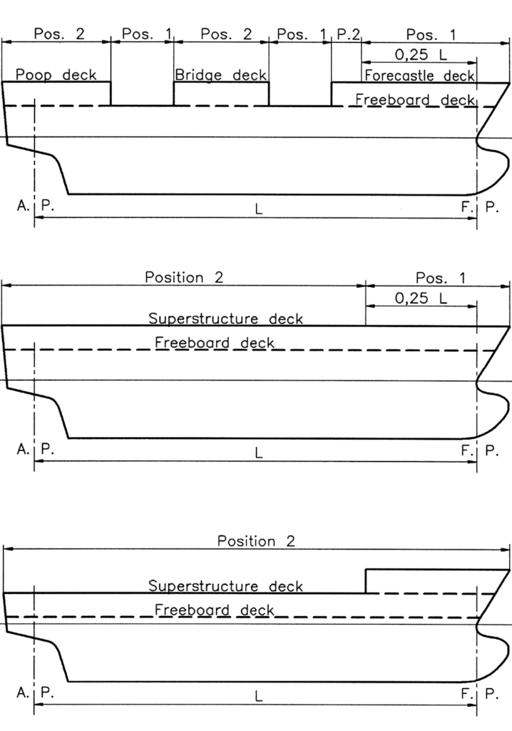
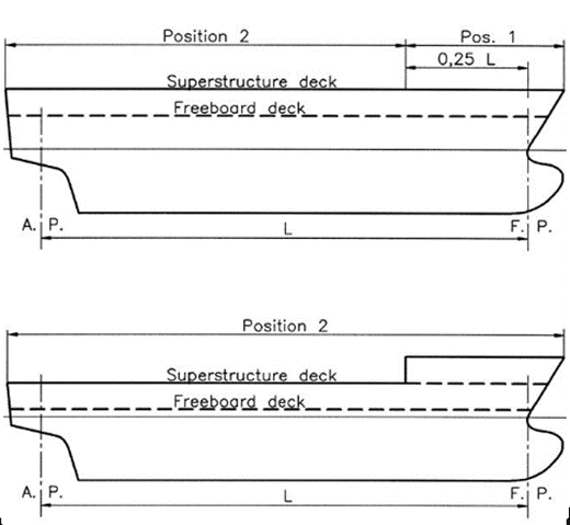
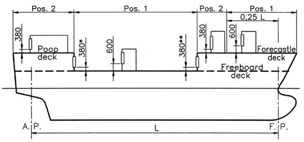
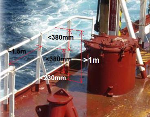
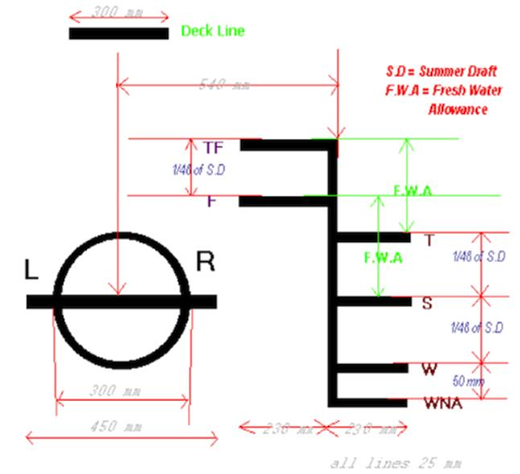


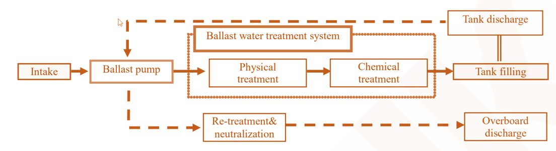
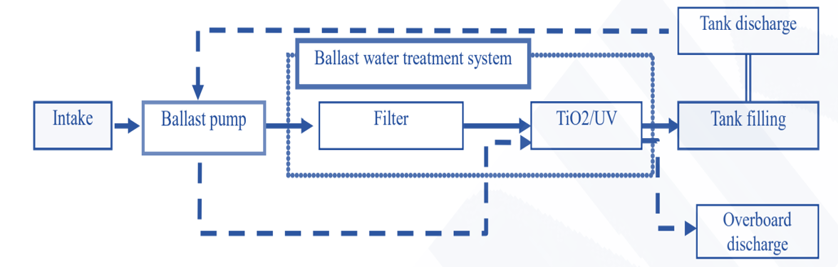
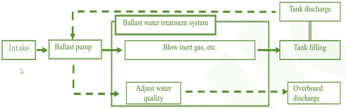
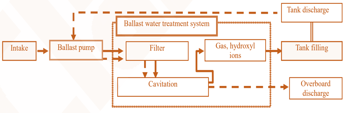
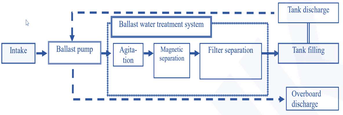