The light falling on the moving parts of any machinery causes it to appear either running slow or in reverse direction or even may appear stationary. This effect is known as the stroboscopic effect.
Reason for Stroboscopic Effect:
In alternating current, for every cycle of current or voltage waves, the waves pass through zero-crossing twice. In our electrical system, we have lamps supplied with 50 Hz or 60 Hz AC supply.
Suppose we are supplying an AC supply of 50 HZ. This means that with a supply frequency of 50 Hz, the lamp will turn off 100 times per second because for 50 Hz supply the voltage or current waves passes through zero-crossings 100 times per second. But, due to the persistence of vision, our eyes do not notice this turning off phenomenon which leads to the stroboscopic effect.
Methods to Avoid Stroboscopic Effect
This pattern of illusions is not allowed in industries as this may lead to accidents. This is the main reason Fluorescent lamps are not preferred in industries.
However, this effect occurs in three-phase as well as single-phase supply. It can be avoided by some simple techniques.
Method to Avoid Stroboscopic Effect in Three-Phase Supply
If the system is supplied with a three-phase supply, adjacent lamps should be fed with a different phase so that the zero instants of the two lamps will not be the same.
Method to Avoid Stroboscopic Effect in Single-Phase Supply
If single-phase supply is only available, then the connection of two adjacent lamps is made such that the two lamps are connected in parallel with the supply.
In one lamp connection, a capacitor or condenser is kept in series with the choke. This makes a phase shift and eliminate the stroboscopic effect
Finding an Earth Fault on a 220V circuit is comparatively difficult than a 440V circuit. The main reason being the lighting circuits found all round the vessel. However, any earth fault alarm with respect to a 220V circuit is usually treated as important but not an emergency.
Check the trueness of the alarm.
Isolate the complete Group start panel for a lighting division one by one.
Check the Earth Fault indicator for status (still faulty or normal).
If faulty, then put on the breaker which is put off earlier and isolate other group start panel for lighting circuit.
Once the group start panel is identified, then individual lighting switches are turned off one by one and checked for the alarm condition.
When any switch when turned off and thus the condition becomes normal, then this lighting circuit is marked and then inspection is done on the particular light for abnormalities.
Ingress of moisture is most common reason for an earth fault.
Alternate Idea: Instead of turning off breakers one by one for the lighting circuit, I followed a method where I turned off all lighting circuit of a particular doubted area. This method helps usually when there are two or more earth faults in 220V lighting circuit. By turning off all the breakers of a particular area, then switching on the breaker one by one will eliminate multiple earth faults.
When I turned off lighting switches one by one, it was difficult for me to identify multiple earth faults.
Once the particular faulty circuit is spotted, then we have to further break them into individual dividable pieces and check them for earth faults. For this as usual, we use megger against earth.
By removing fuse of the two phase lines, each line can be tested and the fault pinned down.
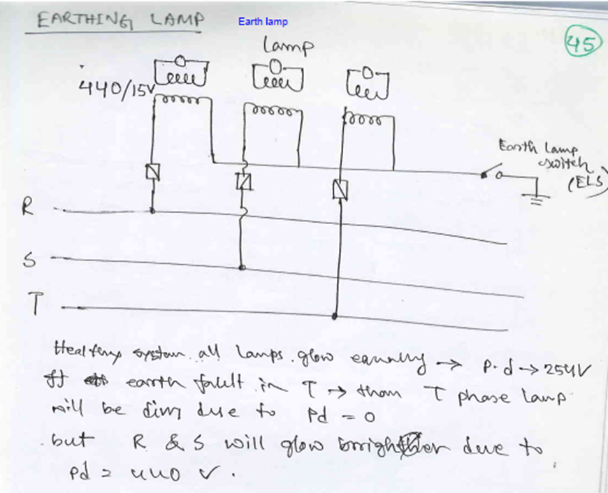
The seriousness of the action to be taken on an Earth Fault depends on the part of the electrical system it affects. Conventional ships which operate on 3 Phase, 440V, have earth fault indicators installed on all three phases. Any earth fault on a 440V system is considered to be a serious trouble and immediate action is required to identify the faulty circuit. Any earth fault on 220V or any low voltage lighting circuit can be considered as important but need not require immediate attention. However, attention should be paid at the next earliest opportunity.
Finding Earth Fault on 440V circuit
Whenever there is an earth fault alarm, immediately inform to electrical officer (if he is on board).
First action is to check the trueness of the alarm. Usually there will be a test button which when pressed, resets the alarm and rechecks the condition of the earth fault.
If the ship is having IAS (Integrated Automation System), check on the computer in the list of events after which the alarm has activated.
If IAS facility is not available, there is only one option of isolating each and every machinery in the 440 V circuit and check whether the earth fault indication returns back to normal.
Isolation of all machinery, which operates on 440V, is not always possible. Certain critical equipment like steering gear and lubricating oil pumps cannot be isolated for when the ship is underway. However changeover can be done from running machinery to the standby one and thus the earth fault can be found.
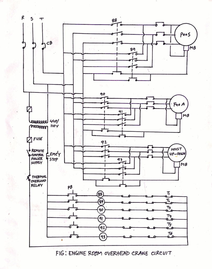
The engine room crane consists of a motor coupled with wire drum so that the motor can lift or lower the crane hoist by winding or unwinding the wire over the drum. The whole system is then fitted in a trolley.
Two pathways are built with a rack and pinion arrangement, both in transverse and longitudinal direction of the engine room and over the main engine, where the trolley is placed so that the whole unit can move fore-aft and port starboard.
A remote is provided so that the crane can be operated from any position, thus allowing the user to keep a safe distance from the lifted load. It is the duty of the responsible engineer onboard to operate the crane and to have regular checks on the safety and working of the crane. Second engineer is responsible for operation, maintenance, and safety checks of the engine room crane.
Safety Features of Engine Room Crane:
.ohcs
1) The most important safety feature of the crane is the electromagnetic fail-safe brakes which do not allow the crane to fall with the load even when there is failure of power. For this:
– Normally centrifugal brakes are fitted inside the rotating drum.
– The brake pads are always in applied state and pushed by magnetic springs when not in operation or when there is a power failure.
– As the crane is operated or the power is supplied, the spring gets pulled inward or compressed due to the electromagnetic effect of the current. This allows the crane to be operated normally.
2) Emergency stop is provided in the remote so that the operator can stop the crane at any time.
3) The motor is fitted with distance limit switch in both transverse and longitudinal direction so that the travel of the trolley limited and hence crane should not overshoot the rack’s end.
4) Mechanical stoppers are provided for both directions in case the electrical distance limit trips fail.
5) The up and down travel of the hook is also attaches with automatic stopper to avoid overloading of the motor.
6) The motor is fitted with thermal protection trip. When the motor windings get overheated, trip will activate saving the motor winding from burning.
7) Load limit switch is also fitted which will trip the motor if the load to be lifted is above the crane capacity.
Operational safety checks
1) It’s the responsibility of senior officers to operate the crane and to make sure all the personnel involve in any lifting operation are at a safe distance during operation of the crane.
2) Additional tools like eye-bolts, shackle, wire sling, belts etc. used for lifting must be checked before use.
3) It should be noted that no one walks or stand below the crane when it is in the loaded condition.
1) Daily checks
Check the lubrication
Check the noise level by operating the crane without load
Check the heat generation
Check all the limits and trips are working properly
Check the contact areas of electrical equipment
Check the brake operation
Check condition of clamp in the hook
2) PMS
Overhauling of motor
Greasing of wires
Renewal of wire ropes
Annual survey
Load test
Grease: Wire ropes, rollers, plain bearings are applied with grease for smooth working.
Oil: Lube oil is used for lubrication of ball bearing and roller bearing of hoisting and slewing gears. Check the oil level regularly and replenish once the level is below the mark.
Inspect the wire rope for twisting, any unstable, any fracture
Inspect The Gears: for any noise, damage on teeth
Check Condition Of Sheave/pulley
Hook condition
Brake condition: The engine room crane is equipped with electromagnetic brake with fail-safe arrangement. This is the most important safety arrangement provided in the crane.
Personal protective equipment (PPE) including insulated gloves, safety goggles, and arc flash protective clothing
Insulated tools specifically designed for high voltage work
Testing and Measurement Devices:
High voltage test probes and multimeters
Insulation resistance testers capable of measuring high voltage equipment
Polarization Index (PI) testing equipment
Note on Polarization Index:
PI testing equipment is designed to measure the insulation resistance of electrical systems over time. The test involves applying a high DC voltage to the insulation and measuring the resistance at specific intervals, typically at 1 minute and 10 minutes. The ratio of these two measurements provides the Polarization Index, which helps evaluate the quality and deterioration of the insulation
Safety and Isolation Tools:
Voltage detectors to verify the absence of voltage before work
Earthing devices for isolating equipment
Locking devices and safety tags for isolation procedures
Diagnostic Equipment:
Partial discharge detectors for insulation testing.
Thermal imaging cameras for identifying potential hotspots
Documentation and Training Aids:
High voltage safety manuals and procedures
Switching strategy documentation
High voltage simulator for training purposes (recommended but not mandatory)
Note: All high voltage instruments must be properly calibrated, maintained, and used only by qualified personnel. Regular inspections and testing of these instruments are essential to ensure their reliability and the safety of the crew working with high voltage systems onboard.
Personnel who are required to routinely test and maintain HV equipment should be trained in the necessary practical safety procedures and certified as qualified for this duty.
Approved safety clothing,
Highly insulating safety gloves
footwear,
eye protection and
hard hat should be used where danger may arise from arcs, hot surfaces and high voltage etc.
Safety equipment should be used by electrical workers includes insulated rubber gloves and mats.
Safety equipment is tested regularly to ensure it is still protecting the user.
A insulated material or rubber mat can be used as a dead front of all electrical installations and equipment.
The access to HV switchboards and equipment must be strictly controlled by using a permit-to-work scheme and isolation procedures together with live-line tests and earthing-down before any work is started. The electrical permit requirements and procedures are similar to permits used to control access in any hot-work situation, e.g. welding, cutting, burning etc. in a potentially hazardous area.
What Are The Additional Safeties On High Voltage System?
> HV circuit breakers either air, gas or vacuum breakers.
> To minimize the size of earth fault current, neutral earthing resistor is using in HV system. Better insulating material like Micalastic is used.
> HV equipment are well designed to have an insulation life of 20 years
> Special relays are provided for overall circuit protection of HV circuit
> Earthing down is essential for HV maintenance which should be declared in Electrical Permit to Work.
The main switchboard (MSB) on a ship is a critical component of the electrical power distribution system. To ensure safe and reliable operation, various safety devices and measures are implemented. Here are the key switchboard safeties and their functions:
Electrical Safety Devices
Circuit Breakers Circuit breakers are automatic shutdown devices that activate during electrical abnormalities. They protect the system by opening the circuit during overloads or short circuits, isolating the fault from the rest of the network.
Fuses Fuses provide short circuit protection and come in various ratings. When current exceeds the safe value, the fuse material melts, isolating the faulty system from the MSB. Typically, fuses are rated at 1.5 times the full load current.
Over Current Relay (OCR) OCRs protect against high currents on local panels and the MSB. They are set to trip at full load current with a time delay, providing protection where low power signals are used as controllers.
Earth Fault Indicators These devices detect and indicate any ground faults in the electrical system, helping to prevent potential hazards.
Under Voltage Relay This relay protects equipment from damage due to low voltage conditions.
Reverse Power Trip This safety feature prevents power from flowing back into the generator, which can cause damage.
Preferential Trip This system automatically sheds non-essential loads during power shortages to maintain critical systems.
Short Circuit Trip This protection activates during short circuit conditions to prevent damage to the electrical system.
Physical Safety Measures
Dead Front Panel This safety feature prevents access to live parts from the front of the switchboard. The panel cannot be opened until the power is switched off.
Insulated Rubber Mats Anti-skid, insulated rubber mats with a minimum thickness of 15 mm are placed in front of and behind the MSB to provide electrical insulation for operators.
Interlocked Door Mechanism The door opening mechanism is interlocked with the power supply, preventing access to live components.
Proper Earthing The MSB and its components must be properly earthed to prevent electrical shock hazards.
Ebonite Rod This non-conductive rod is used to remove static charges from the switchboard.
Additional Safety Measures
Proper Ventilation and Illumination The MSB location should have good ventilation and lighting to ensure safe operation and maintenance.
No Water or Oil Pipes Nearby Water, steam, or oil pipelines should not pass in the vicinity of the switchboard to prevent potential hazards.
Safety Charts and Signage Charts indicating procedures for electric shock treatment and danger signs should be prominently displayed near the MSB. By implementing these safety devices and measures, ship operators can significantly reduce the risk of electrical accidents and ensure the reliable operation of the ship’s power distribution system.
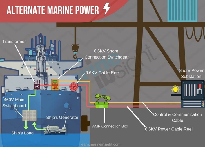
Alternate Maritime Power or AMP is an anti-pollution measure which helps in reducing air pollution generated from diesel generators by using shore electric power as a substitute.
AMP is used when the ship is stay at port, required to stop idling the engines (low load operation) and transfer the power source to a land base. This allows the ship to switch-off its generators. It helps in significant reduction in noise and air pollution.
AMP done with the help of supply cables that are plugged into an electricity supply board in the port on one end and to the ship’s power supply board on the other. The process is called cold ironing.
At present, there are four different variations in the AMP that is provided from the port to a ship.
11000 Volts of AC (Alternate Current)
6600 Volts of AC
660 Volts of AC
440 Volts of AC
The AMP system comprises major components such as – Cable Reel, Reel Control Centre & Pendant, Amp Connection Box, 6600v Shore Panel, Transformer, Main Switch Board, Amp Control Panel.
1. Electrical overload caused by excessive voltage supply or overwork by drawing more current will lead to overheating issues. As the motor works harder or under unusual load, heat will be the chief byproduct, leading to failure.
3. Contamination of dust and debris will raise the internal temperature of a motor and keep it from cooling, which leads to excessive heat over a longer period of time. This generally occurs without proper maintenance or venting for particles.
A lack of ventilation: If there is something blocking the ventilation holes for your electric motor, then hot air won’t escape and will build up within the system, causing damage. Scheduling regular maintenance on your motor can help reduce this risk.
4. Start-stop frequency plays a big role in heat damage. Excessively starting, stopping, and starting the motor again won’t allow it to cool properly. The result is a high-heat environment that wears on the integrity of components.
5. Vibration from a condition like soft foot leads to excessive heat. If vibrations are severe enough, they’ll raise temperatures to unsafe levels and stress components beyond their capacity for heat.
6. High ambient temperatures
If a motor is running in a much warmer environment than it was designed for, it can overheat because the ambient temperatures will make it more difficult for the motor to cool down properly. Check the insulation class of your motor (found on the motor’s nameplate).
7. High or low voltage supply
Power supply may be insufficient due to amp draw. In order to overcome load or inertia at a stand-still, the motor’s running current will be too much high under load. Incorrect voltage supply will make the motor work harder and could cause it to overheat.
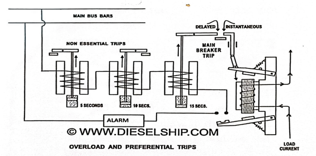
Preferential tripping in a Marine electrical distribution system are designed to disconnect non-essential circuits (e.g. Breakers controlling air conditioning, galley power, blowers, refrigeration etc.) in the event of partial overload or partial failure of the supply with the aim of preventing operation of the main breaker trip and loss of power on essential services.
A method for operating all the overall type trips from one load current carrying coil uses to instantaneous trip levers.
• The top Lever is arranged as an instantaneous short circuit trip and opens the breaker directly through mechanical linkages.
• The bottom lever process instantly at the lower overload current setting and by doing so, complete the circuit through two or more non essential circuit trips and a main breaker trip all incorporating dashpot time delay.
• These relays will trip out non essentials at 5 and 10 second intervals based on their priority and finally if the overload persists the main breaker after 15 seconds.
• Warning of overload is given by the alarm overload protection is provided on both poles
• The current passes through the electromagnetic coil and the linkage are kept from contacting using a spring arrangement. As soon as the current value increases the limit the electromagnetic coil pulls the linkage up against the spring force and operates the instantaneous circuit and the alarm system. The lower linkage complete the circuit for the preferential trip circuit
• The current passes through the coil in the preferential trip circuit which pulls the Piston in the dashpot arrangement. The movement of this piston is governed by the diameter of the orifice and the time delay made by the same.
• The preferential trip operates at 5,10 and 15 seconds and the load is removed accordingly if the overload Steel pursuits then an audible & visual alarm is sounded.
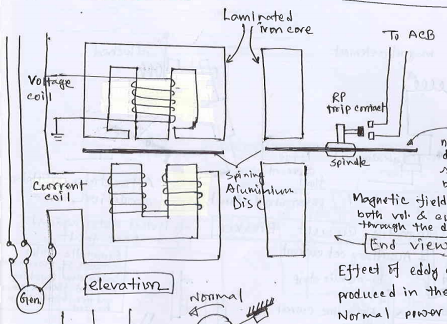
The Reverse Power Trip Relay is a crucial protective device used in electrical systems, particularly for generators. It operates based on the principles of Faraday’s law of induction and Lenz’s law.
Working Principle
Eddy Currents: Loops of electrical current induced within a conductor due to Faraday’s law of induction.
Lenz’s Law: An eddy current creates a magnetic field that opposes the magnetic field that created it.
Components and Structure
Aluminum Disc: A lightweight, non-magnetic disc mounted on a spindle with low-friction bearings.
Magnetic Field Coils: Both voltage and current coils produce magnetic fields that pass through the disc.
Trip Contacts: Located on the spindle.
Stopper: The disc rests against this under normal power flow conditions.
Operation
Normal Power Flow:
The disc bears against the stopper.
Trip contacts on the spindle remain open.
Reverse Power Condition:
Eddy Current Generation: Magnetic fields from the coils pass through the disc, causing eddy currents.
Torque Production: The interaction between the eddy currents and magnetic fields produces a torque effect on the disc.
Disc Rotation: When power reverses, the disc rotates away from the stopper.
Contact Closure: As the disc rotates, the contacts close, triggering the circuit breaker to trip.
Safety Feature: To prevent unnecessary tripping due to power surges during synchronization, the relay incorporates a time delay of 5 seconds.
Reverse Power Relay (RPR) detailed Operation:
Basic Principle
A reverse power relay detects when power flows in the reverse direction from the load back to the generator, which can damage the generator. It protects the system by disconnecting the generator when reverse power is detected.
Components
Voltage coil (connected in parallel)
Current coil (connected in series)
Aluminum disc
Trip contacts
Magnetic Field Generation
Voltage coil:
More turns, higher inductance
Induced current lags by ~90°
Produces weaker magnetic field
Current coil:
Fewer turns, lower inductance
Induced current lags less
Produces stronger magnetic field
The magnetic fields from both coils are approximately 90° out of phase.
Disc Movement
Eddy currents are induced in the aluminum disc by the magnetic fields
Torque is generated on the disc (Lorentz force)
Under normal power flow, disc rotation is restricted by stoppers
During reverse power, disc rotates in opposite direction
Trip Mechanism
Disc rotation closes trip contacts when reverse power occurs
This activates the protection system to disconnect the generator
Setting the Reverse Power Relay
Typically set to 20-50% of the prime mover’s motoring power
Motoring power: Power required to drive the prime mover at rated RPM
Setting obtained from prime mover manufacturer specifications
Considerations for Ships
Marine applications require careful calibration
Settings may vary based on ship type and operating conditions
Regular testing and maintenance are crucial for reliability
Reverse power is a condition in which power flows from the bus bar into the generator, contrary to the normal power flow direction. This phenomenon can occur due to various reasons and has significant implications for electrical system operation and safety.
Primary Causes of Reverse Power
1. Prime Mover Failure
Occurs when the engine or turbine driving the generator fails
Common causes include:
Fuel starvation in the prime mover
Speed controller malfunction
Mechanical breakdown of the prime mover
2. Motoring Condition
Happens when a generator in a synchronized system experiences prime mover failure
The generator draws power from the bus bar and runs as a motor, driving the failed prime mover
Occurs because all synchronized generators maintain the same frequency
Any drop in frequency in one generator causes other power sources to pump power into it
3. Synchronization Issues
Can happen during the process of connecting a generator to the bus bar
If the incoming machine’s frequency is slightly lower than the bus bar frequency when the breaker closes, power will flow from the bus bar to the machine
Mechanism of Reverse Power
In a synchronized condition, all generators operate at the same frequency. If one generator’s frequency drops due to prime mover failure, other power sources on the bus bar will automatically supply power to maintain system stability. This reverse flow of power is detected by the reverse power relay.
Prevention and Best Practices
To prevent reverse power during synchronization:
The incoming machine’s frequency should be kept slightly higher than the bus bar frequency
This is often referred to as running in the “too fast” direction
Ensures the machine takes on load as soon as the breaker closes
Importance of Reverse Power Protection
Reverse power protection is crucial because:
It prevents damage to the prime mover (engine or turbine)
It avoids unnecessary power consumption by a non-producing generator
It helps maintain overall system stability and efficiency
Detection and Protection
Reverse power is typically detected and protected against using:
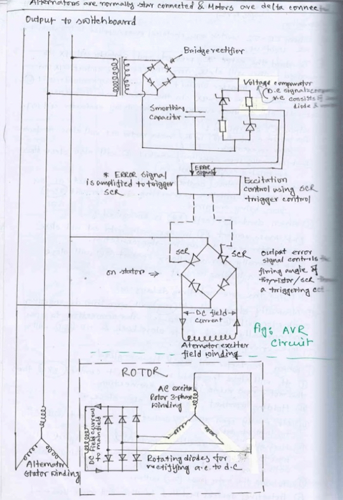
The alternator, which is typically star-connected, generates AC voltage through electromagnetic induction as it rotates.
The generated voltage is fed to the main transformer, which steps up or steps down the voltage to the desired level for distribution.
Voltage Regulation
The AVR unit continuously monitors the output voltage of the alternator.
If the output voltage deviates from the desired setpoint, the AVR adjusts the excitation current supplied to the exciter.
If the output voltage is too low, the AVR increases the excitation current.
If the output voltage is too high, the AVR decreases the excitation current.
The exciter, which is essentially a smaller generator, provides the magnetic field for the alternator rotor.
By adjusting the excitation current, the AVR effectively controls the strength of the rotor’s magnetic field, which in turn regulates the output voltage of the alternator.
Output
The regulated voltage from the alternator is fed to the main transformer.
The transformer steps the voltage up or down as needed for distribution to the switchboard and connected loads.
By continuously monitoring and adjusting the excitation current, the AVR maintains a stable output voltage from the alternator despite variations in load or other factors. This ensures a reliable and consistent power supply to the connected equipment.
Smoothing Capacitor
Smoothing capacitors are commonly used in power supply circuits to reduce voltage ripple and provide a more stable DC output.
Function of a Smoothing Capacitor
The main functions of a smoothing capacitor are:
Ripple Reduction: It reduces the voltage fluctuations (ripple) in the rectified DC output.
Voltage Stabilization: It helps maintain a more consistent voltage level by storing and releasing charge.
Current Smoothing: It smooths out the pulsating DC current, making it more suitable for electronic circuits.
How It Works
Charging: The capacitor charges when the rectified voltage rises above the capacitor’s stored voltage.
Discharging: It discharges when the rectified voltage falls, providing current to the load.
Continuous Cycle: This charge-discharge cycle happens rapidly, effectively filling in the gaps in the rectified waveform.
Based on the circuit diagram and the query, I’ll explain the voltage comparator in the context of the Automatic Voltage Regulator (AVR) circuit:
Voltage Comparator in AVR
Its function is to compare the actual output voltage of the alternator with a reference voltage.
How It Works
Voltage Sensing: The comparator continuously monitors the alternator’s output voltage.
Reference Voltage: It compares this sensed voltage against a preset reference voltage, which represents the desired output voltage level.
Comparison: The comparator determines whether the actual voltage is higher or lower than the reference voltage.
Output Signal: Based on this comparison, it generates an error signal.
Control Action: This error signal is used to adjust the excitation current supplied to the exciter.
Function in the AVR System
Voltage Regulation: The comparator’s output helps maintain a constant voltage output from the alternator
Error Detection: It quickly detects any deviation from the desired voltage level.
Feedback Control: The comparator’s output initiates the feedback loop that adjusts the excitation current.
Direct-on-line starters is the most commonly used, the most usual consideration being whether the generator and the distribution system can withstand the starting current. In the case of loads with high inertia (e.g. oil separators) the starting time may also be a factor.
The starting current is 5 – 8 times the full load current and the heating of windings is 25 – 64 times normal due to I2R effect. Furthermore, at the instant of starting, there is not windage and radiation. A long starting period may result in overheating. Representative starting periods may be 15 seconds for a 1.5 kW motor and 25 seconds for a 30 kW motor with an initial starting current of not more than 6 times full load current.
For these reasons, it is desirable not to make repeated successive starts without intervening periods of cooling.
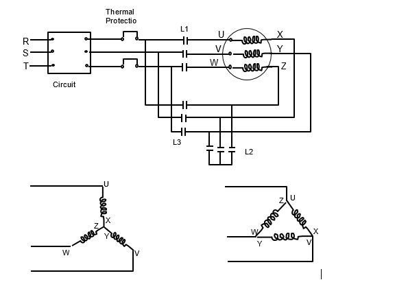
In the starting position, the voltage across each phase windings is 58% of the line voltage as it is star connected, i.e. with consequent reduction in starting current. It is 1/3 the starting than delta.
Operation of Star-Delta Starter
At starting contactor L 2 closes and time delay (not shown) is energized.
Line contactor L1 closes next.
Motor starts on reduced voltage due to star connection of motor windings.
At the end of time delay period, star contactor L2 opens.
Immediately afterwards, contactor L3 closes.
Motor now runs on full voltage and on delta connections.
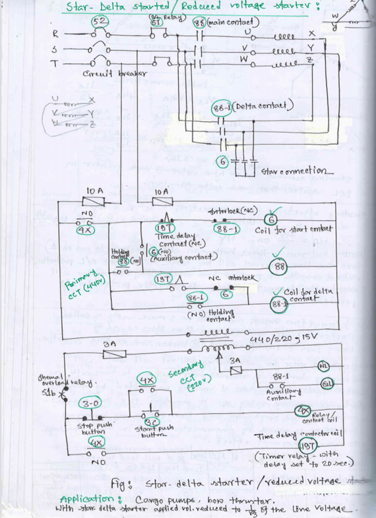
Principle of Operation
operation of the star-delta starter is explained below:
a) When the circuit breaker 52 is switched on, electrical power will be supplied to the transformer and the WL lamp will be lighted up.
b) To start the motor, push-button 3C is depressed and contactor coil 4X is energized. This will close normally-open contact 4X in the transformer primary circuit and energizing contactor coil 6. In the meantime, normally open contact 4X in the transformer secondary circuit will also close thus energizing time-delay contactor coil 19T.
c) When contactor coil 6 is energized:
Main contacts 6 in the main motor circuit will close to form the star connection.
Normally open auxiliary contact 6 will also close thus energizing contactor coil 88.
Normally closed contact 6 will open to act as an electrical interlock preventing contactor coil 88-1 from being energized.
d) When contactor coil 88 is energized:
i. Main contacts 88 in the main motor circuit will close and the motor begins to run in star connection.
ii. Normally-open auxiliary contact 88 will also close acting as a holding contact.
e) After the pre-set time delay:
Normally-closed contact 19T will open thus de-energizing contactor coil 6. This causes the star-connection to open and the normally-closed contact 6 to close back.
f) When contactor coil 88-1 is energized:
i. It will close the main motor circuit contacts 88-1; thus, the motor now runs in the delta connection.
ii. Holding contact 88-1 will also close.
iii. Normally-open auxiliary contact 88-1 closes to light up the GL lamp.
iv. Normally-closed contact 88-1 will open to prevent contactor coil 6 from energizing thus acting as an electrical interlock.
To stop the motor, depress push-button 3-0.
g) Protective devices installed in the circuit are thermal overload relay 51 and fuses.
Effect of Full Voltage Starting and Reduced Voltage Starting
With full voltage starting, as used in direct-on-line starters, very large current surges of 6 – 8 times full load current occurs.
With starting of large motors using direct-on-line starters, large voltage dip takes place. This voltage disturbance may result in malfunction of other electrical equipment connected to the supply.
Reduced-voltage starters, such as the star-delta starter or the autotransformer starter, are used to start large motors, e.g. cargo pumps and bow thrusters.
With star-delta starters, the applied voltage is reduced to of the line voltage at start. If this is done, both starting torque and starting current are reduced to 1/3 of what they would have been had the motor been switched direct-on-line from the main.
6. For example, suppose a squirrel cage motor is such that if switched on to the mains it develops 90% of its normal full load torque and takes 6 times its normal full load current from the mains. On star-delta starting, it would develop 90/3 i.e. 30% of its normal full load torque and takes 6/3 times its normal full load current.
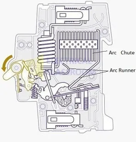
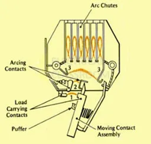
Arc chute is a set of metal plates that are arranged in parallel and mutually insulated from each other, which can divide, cool and safely extinguish an electric arc. They are also known as arc splitters and arc dividers. Arc chutes can be found inside circuit breakers, contactors, isolators and other high current interruption devices.
On the basis of their operation, marine scrubbers can be classified into Wet and Dry scrubbers. Dry scrubbers employ solid lime as the alkaline scrubbing material which removes sulphur dioxide from exhaust gasses. Wet scrubbers use water which is sprayed into the exhaust gas for the same purpose.
Wet scrubbers are further classified into closed-loop or open loop scrubbers. In close looped scrubbers, fresh water or sea water can be used as the scrubbing liquid. When Fresh water is used in closed loop scrubbers, the quality of water surrounding the ship has no effect on the performance and the effluent emissions of the scrubber. Open-loop scrubbers consume sea water in the scrubbing process.
Hybrid scrubbers can utilise both closed and open running modes either at the same time or by switching between the two. Seawater hybrid scrubbers can be operated both in closed or open mode with seawater used as the scrubbing medium.
Wet Scrubbers
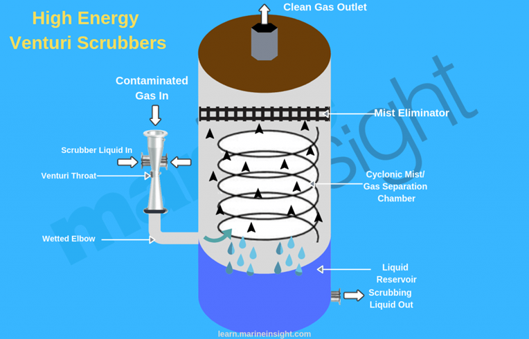
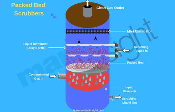
Inside a wet scrubber, the scrubbing liquid used may be sea water or fresh water with chemical additives. The most commonly used additives used are caustic soda (NaOH) and Limestone (CaCO3). Scrubbing liquid is sprayed into the exhaust gas stream through nozzles to distribute it effectively. In most scrubbers the design is such that the scrubbing liquid moves downstream, however, scrubbers with an upstream movement of scrubbing liquids are
The exhaust inlet of the scrubber can be made in the form of a venturi, as shown in Figure 2.1, in which the gas enters at the top and water is sprayed in the high exhaust gas speed areas at the neck or above the neck in the form of a spray. An inline scrubber is shown in figure 2.2.
The exhaust intake is either on the side or the bottom of the tower. The designs ensure that the sulphur oxides present in the exhaust are passed through the scrubbing liquid; reacting with it to form sulphuric acid. When diluted with alkaline seawater, sulphuric acid which is highly corrosive in nature can be neutralised.
The wash water is discharged into the open sea after being treated in a separator to remove any sludge from it and the cleaned exhaust passes out of the system. Mist eliminators are used in scrubbing towers to remove any acid mist that forms in the chamber by separating droplets that are present in the inlet gas from the outlet gas stream.
Figure 2.2
MARPOL regulations require that the wash water used has to be monitored before being discharged to ensure that its PH value is not too low. Since the alkalinity of seawater varies due to the number of reasons such as the distance from land, volcanic activity, marine life present in it etc, wet scrubbers are divided into two types; open loop and closed loop systems. Both these systems have been combined into a hybrid system, which can employ the most suitable scrubbing action depending upon the conditions of the voyage.
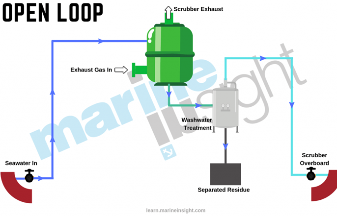
Open Loop Scrubber System
This system uses seawater as the scrubbing and neutralising medium, no other chemicals are required for desulphurization of gasses. The exhaust stream from the engine or boiler passes into the scrubber and is treated with only alkaline seawater only. The volume of this seawater depends upon the size of the engine and its power output.
The system is extremely effective but requires large pumping capacity as the amount of seawater required is quite high. An open loop system works perfectly satisfactorily when the seawater used for scrubbing has sufficient alkalinity. However, sea water which is at high ambient temperature, fresh water and even brackish water, is not effective and cannot be used. An open loop scrubber for these reasons is not considered as a suitable technology for areas such as the Baltic where salinity levels are not high.
1. It has very few moving parts, the design is simple and easy to install on board. 2. Apart from de-fouling and operational checks, the system requires very less maintenance 3. This system does not require storage for waste materials
Disadvantages:
Cooling of the exhaust gas is a problem faced by wet scrubber systems.
The operation of the system depends upon the alkalinity of water available and is not suitable to be employed in all conditions.
A very large volume of sea water is required to obtain efficient cleaning and hence the system consumes very high power.
In ECA zones and ports, higher costing fuel has to be consumed.
Closed Loop Scrubber System
It works on similar principals to an open loop system; it uses fresh water treated with a chemical (usually sodium hydroxide) instead of seawater as the scrubbing media. The SOx from the exhaust gas stream is converted into harmless sodium sulphate. Before being re-circulated for use, the wash water from a closed loop scrubber system is passed through a process tank where it is cleaned.
The process tank is also needed for the operation of a circulation pump that prevents pump suction pressure from sinking too low.
Ships can either carry fresh water in tanks or generate the required water from freshwater generators present on board. Small amounts of wash water are removed at regular intervals to holding tanks where fresh water can be added to avoid the build-up of sodium sulphate in the system.
A closed-loop system requires almost half the volume of wash water than that of the open loop version, however, more tanks are required. These include a process tank or buffer tank, a holding tank through which discharge to sea is prohibited and also a storage tank capable of regulating its temperature between 20º and 50ºC for the sodium hydroxide which is usually used as a 50% aqueous solution
Dry sodium hydroxide also requires large storage space. The hybrid system is a combination of both wet types that can operate as an open loop system when water conditions and the discharge regulations allow and as a closed loop system at other times. Hybrid systems are hence proving to be the most popular because of their ability to cope with different conditions.
1. Very less maintenance is required. 2. It is independent of the operating environment of the vessel. 3. Cooling of exhaust gas is a problem with wet scrubbing systems.
Disadvantages
It requires storage space (buffer tank) to hold waste water until it can be discharged
Selective catalytic reduction systems must operate before wet scrubbers.
Fitting the system together, especially for dual-fuel engines can be quite complex.
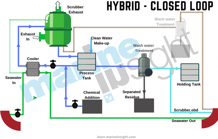
Hybrid Scrubber System
These systems offer a simple solution for retrofitting vessels with scrubbers that are capable of operation on both open loop and closed loop configurations. These systems run on open loop mode at sea and closed loop mode in ECA zones and ports and their use can be switched with ease. As the system can run on lower costing fuels for longer periods of time and around the world, they can overcome their high initial costs in order to economically meet with the international regulations.
Advantages:
Suitable for long and short voyages around the world
Ships with Hybrid scrubbing systems can spend more time in ECA zones and on port than those with open loop systems 3. Can use lower costing HFO (Heavy Fuel Oil) all of the time.
Disadvantages
1. More structural modifications are needed to employ this system. 2. Requires large storage space for chemicals and additives. 3. The system has a high installation time and cost.
Dry Scrubbers
In these types of scrubbers, water is not used as a scrubbing material, instead, pellets of hydrated lime are used to remove sulphur.
The scrubbers are at a high temperature than their wet counterparts and this has a benefit that the scrubber burns off any soot and oily residues in the system. The calcium present in caustic lime granulates reacts with the sulphur dioxide in the exhaust gas to form calcium sulphite.
Calcium sulphite is then air-oxidized to form calcium sulphate dehydrate, which with water forms gypsum. The used pellets are stored on board for discharge at ports, however, they are not considered a waste as the gypsum formed can be used as a fertiliser and as construction material.
Dry scrubber systems consume less power than wet systems as they do not require circulation pumps. However, they weigh much more than wet systems.
1. There is efficient removal of nitrogen and sulphur oxides 2. This type of system does not result in the production of liquid effluent that must be disposed of overboard. 3. The Gypsum obtained after the exhaust gas cleaning process can be sold for use in various industrial applications
Disadvantages
They require significant onboard storage to handle the dry bulk reactants and products associated with the process. There must be a readily available supply of the reactants. the reactants used are costly, especially urea for NOx abatement and calcium hydroxide for SOx abatement
Draw samples from a connection that comes directly out of the main oil supply line to the engine.
Always sample for the same point.
Sample only when the oil is up to its operating temperature with the engine running.
Depending upon the draw off point, sufficient amount of oil should be drained out of the line prior to drawing the sample.
The sample should be filled into a chemically cleaned container after it is rinsed with sample oil and immediately closed.
The container should be attached with a label as follows:
Records for Sample
Date of sample drawn
Point of sample drawn
Temperature of sample drawn
Type of oil
Type of machinery use
The period of time since the last renewal of oils.
Avoid sampling from places where the oil may be stagnant or have little or no flow, such as sumps, auxiliary smaller pipelines, purifier suction or discharge lines, drain cocks of filters, coolers etc.
Also avoid sampling while engine is stopped.
Microbial Degradation of lubricating oil
.microbial degradation
Stagnant lube oil for long periods in humid conditions can result in bacterial growth due to the presence of water
Indication
Oil appearance looks slimy and greyish and is indicated by the ‘rotten egg’ odour
Prevention
Oil must be heated and circulated periodically especially when a ship is laid up
Lube oil properties
.aecc lo .aux eng lo .ae lo
.lo properties .lop
High oxidation and thermal resistance to perform at elevated temperatures.
High Viscosity index so that it does not vary much with temperature.
Appropriate viscosity to meet liner lubrication as well as bearing lubrication 12cst at 100 degree
High detergency properties so that it softens and takes away all the deposits formed
High dispersancy properties so that it keeps all the deposits in suspension so that it can be removed easily by purification.
Higher flash point as it comes into contact with the combustion gases degree
TBN value according to sulphur content in fuel 10-30 mgKOH/g
Antifoam properties as the oil tends to have higher deposits
Extreme pressure and anti-wear additives for maintaining boundary lubrication between piston rings and liner
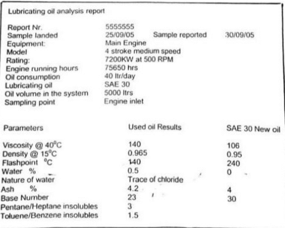
b) Analyze the condition of this oil
Viscosity:
106
Viscosity can increase due to-
High insoluble content
HFO contamination due to leaky injectors, worn fuel p/p plunger & barrels
Piston blow past
Oxidation due to ageing & high operating temp
Water contamination (emulsification)
For information: viscosity can decrease by gas oil contamination during prolong running in ECA area.
Density:
0.95
Density can increase due to-
High insoluble content
HFO contamination due to leaky injectors, worn fuel p/p plunger & barrels
Piston blow past
Water contamination (emulsification)
Flash point:
240 degree C
Flashpoint can reduce, Main suspect FO contamination due to
Crankcase breather pipe condensation as atmosphere has saline nature
Inefficient operation of purifier
Possible but do not suspect leakages due to steam or engine cooling water leakage as this may increase the base number
allowable FW content max 0.2%, for short period 0.5%
Ash:
4 mg/kg
Can Increase due to –
HFO contamination due to leaky injectors, worn fuel p/p plunger & barrels
Blow past
Rust in the sump tank
Base number:
30
Can reduce due to
Insufficient oil volume in circulation
Irregular top up of sump
Fuel contamination and sulphur in HFO can reduce TBN
Max +100%, min -30% of initial value.
Insoluble:
Max 2%.
The amount of insoluble ingredients in the oil is checked as follows.
Equal parts of oil samples are diluted with [Toluene/benzene] and [pentane / heptane].
As oxidized oil is only soluble in benzene and not in pentane or heptane the difference in the amount of insoluble is indicatives of the degree of oxidation.
Pentane /heptane Insoluble:
Indication of oxidation & the metallic deposits/ solid contaminant present
Max 2%
Toluene/ benzene insoluble:
Indication of the solid contaminants
Max 1%
P/H –T/B insoluble:
3 –1.5 = 1.5 is the Indication of the rate of oxidation that has taken place
Limit max. 1%
Main possibility due to iia
Insufficient volume
Improper top-up
Ageing of oil
Batch Purification
.bp .batch purification
.batch purification
When it is done
Insoluble content is too high
Recommended in Lub oil analysis report.
Routinely carried out in dry Dock.
Before commencement transfer in settling tank
Discusses with master and technical superintendent
Job risk assessment to be carried out
Work permit to be taken
Immobilization permit to be taken
Ensure the Lube oil settling tank is empty.
Open the manhole door for setting tank.
Carry out proper ventilation
Follow enclosed space entry permit for settling tank.
Clean the setting tank with lint-free Rags.
Settling tank walls and top should be free of rust.
Settling tank heating coil tried out confirm no leakage.
Drain cock is functioning well
Before purification procedure
Use the lub oil transfer pump to transfer enter sump oil to the settling tank.
Take a sample at setting tank for on-board test for water, TBN and viscosity.
Note down the value for this test.
Open steam heating to the settling tank and set temperature 60 to 70 degree Celsius
Allow oil to settle for at least 24 hours
Drain the tank frequently until water stops coming out
Purification
Start settling tank to settling tank purification.
Keep purifier feed rate at minimum on 1/3 of maximum capacity.
Continue purification as long as time permits.
Sump cleaning
Open up the void tank manhole cover
Carry out ventilation for few hours.
Follow the enclosed space entry permit procedure for void tank.
Take portable oxygen gas detector, before entry into enclosed space calibrate in atmosphere condition.
One responsible person must standby outside enclosed space
Communication must be established with the person outside and the person in bridge.
After inspection void tank open the manhole cover for sump tank.
Carry out ventilation of sump tank and follow enclosed space entry procedure separately.
Entre the sump tank for cleaning.
Scoop all the sludge and use lint free rags to clean the tank with emphasis on the bottom of the tank.
Box up the sump tank manhole cover after cleaning.
Transfer LO to sump
Take a sample at settling tank and carry out on-board test. If the test is satisfactory or engine needs to be ready, start purifier from settling tank to sump tank.
The void tank manhole cover to be closed only after the sump tank is filled and its manhole has no leakage.
Mean time clean all LO filters in the system.
Onboard Lube Oil Tests
.lo test
.lube oil test
For all types of lube oils on ships, following Lube oil tests are carried out:
1. Water Content test
5 ml of sample is taken inside digital water content meter mixed with 15 ml of reagent containing paraffin or toluene. Before closing the lid of the digital meter, a sealed sachet containing calcium Hydride is kept and container closed tight. The meter is shaken by hand and the pressure rise due to the chemical reaction in the test container is shown as water percentage in the digital display.
2. pH Test
It is done by using a pH paper which changes colour once in contact with oil and it is then compared with standard values. This test determines the reserve alkalinity of the oil sample.
3. Viscosity Test
This test is performed by using a Flow stick in which two paths are provided for flow of oil side by side. In one path fresh oil is filled and in other side path used sample oil is filled. Now the flow stick is tilted allowing oil on both paths flowing in the direction of the tilt due to gravity. A finish point is provided along with reference points along the flow stick and the position of used oil is checked when fresh oil reaches the finish point.
Q. During watch main engine lube oil level go down, what are your actions?
Check lube oil sump tank level manually, confirm actual level.
If low, check for possible lube oil leakages
Check lube oil purifier
Check under piston space drain for piston cooling oil leakage.
Check lube oil pump for possible leakages
Stop engine if problem found in main engine component and rectify.
If problem in LO purifier, stop purifier and clean it.
Q. Difference between Stern tube lube oil and crankcase oil
.mecc oil .stern tube oil .st oil
ME crankcase oil
Stern Tube Lube Oil
Excellent thermal and oxidation stability and detergency
Good corrosion protection
Excellent deposit control of oil-cooled piston under crown
Excellent wear protection for gears and Bearings
Excellent detergency (Clean crankcase)
Excellent viscosity temperature behaviour, high viscosity index (VI)
Excellent dispersancy -Extended oil life due to efficient water separating properties ()
Miscible with mineral oil and polyalphaolefin gear oil
Rust and corrosion properties (anti-oxidant)
Natural dissolving properties
Good wear protection
Highest shear stability
Approved by major engine manufacturers
Based on renewable resources
alkalinity is sufficient to neutralize crankcase contamination (TBN)
– Maintain oil-water interface too close to clean oil outlet
3. Condensation due to high humidity
4. Leakage through sump diaphragm due to over tightening or fretting
5. Leakage of bilge:
– Through sounding gauge
– Through expansion bellows fitted between engine & tank top
6. Leakage of L.O. cooler (Tube or gasket)
7. Purifier sealing water solenoid valve leaking
8. Mist box drain choked or Rainwater accumulation in mist box
9. Lube oil purifier steam heater leakage.
Effects:
1. Deterioration in lube oil properties
2. Reduction in load carrying capacity.
3. Reduction in cooling effect.
4. Sludge formation
5. Corrosion in various parts of machinery
6. Worst of all leading to microbial degradation
Corrective/Preventive Actions:
1. Identify & rectify the actual source of leakage (root cause)
2. Centrifuge at optimal throughput and maintain temperature at about 80°C
3. Monitor through shipboard lube oil test for water
4. Batch purification at 1st opportunity
Batch Purification Procedure:
1. Discuss with master & technical manager
2. Immobilization permission
3. Risk assessment carried
4. Discussion in toolbox meeting
5. Relevant work permit to be made
6. Proper ventilation of L.O. settling TK
7. Enclosed space entry permit before entering L.O. sett TK
8. Inspect L.O. sett. TK (Top & walls should be rust free)
9. Clean with lint free rags
10. Sett TK heating coil to be pressure tested for leakage
11. Sett. TK drain cock must be functioning properly
12. Transfer all sump oil to sett. TK from sump by using L.O. transfer p/p
13. Take a sample from sett. TK for onboard lube oil test for water, TBN, Viscosity & spot test
14. Note down the values of this test
15. Steam open for sett TK heating. Maintain temp. 60-70°C
16. Allow oil to settle at least 24 hours
17. Drain the TK frequently until water stops coming
18. Clean the purifier before use & monitor
19. Start purification from sett. to settling TK
20. Keep purifier at optimal throughput and temperature at about 90°C
21. Continue purification for as long as time permits
22. If onboard test result come satisfactory, send sample for lab analysis for detailed test
Sump Cleaning:
1. Open void tank manhole cover & do proper ventilation
2. Prepare enclosed space entry permit upon satisfactory gas test
3. Enter void tank and open sump tank manhole cover
4. Again do proper ventilation & enclose space entry permit made after gas test
5. Enter lub oil sump tk for cleaning
6. Scoop off all the sludge & use lint free rags to clean tank with emphasis on the bottom and loose rust at the ceiling
7. Box up sump tk manhole door
8. Void tk manhole cover to be closed only after sump tk is filled and its manhole has no leakage
9. Take sample from L.O. sett. tk for shipboard lube oil test. If test result is satisfactory and engine needs to be ready, start purification from setting to sump tk
10. Simultaneously, clean all lube oil filter & coolers in the system
11. Update the work done on PMS. Make enough photographic evidence
12. Make a clear report & send it to office
Vessel Options:
1. Upon satisfactory test result from onboard test & shore analysis, discussing with office, vessel may use the oil from sett. TK or dispose it
– Can add partial amount of fresh new oil upon office approval
2. Use fresh batch of new oil with complete charge in sump
Note: It is advisable to use one or more crankshaft bearings at earliest opportunity if the symptoms of emulsification are visible.