BEARING:

Bearing Clearance Check:

.bearing clearance .bc check

Before undertaking any work on the engine, the safety check should be carried out: 

  1. Take Permission to immobilize engine.
  2. Risk assessment should be carried out.
  3. Work permit to be taken.
  4. Starting air shut off and locked off. 
  5. Open the indicator cock.
  6. Engine cooled down sufficiently to allow L.O pump to be shut down.
  7. Check that no one is working on the vicinity of the shafting. 
  8. Take propeller clearance from bridge.
  9. All lifting gear, shackles etc checked for defects and check they are within certification.

Tool box meeting should be carried out, only the person in charge of operation is to operate the turning gear.

Bearing area need need to give particular attention

  • Bottom half of the cross-head bearing
  • Top half of crank pin bearing
  • Bottom half of main bearing

Main Bearing Clearance:

.main bearing clearance  .mbc

There are various types of methods adopted by different marine engine manufacturers to measure the clearance of main bearing of marine engine.

1)  Bridge with Depth Gauge

This method is used in SULZER 2 stroke marine engines where the bearing ‘s shell is removed along with the keep (the bearing shell is lined with the keep). After that a bridge is fitted over the top of journal pin, from port to starboard, making a bridge over the crankshaft with two ends supported on the cross girder.

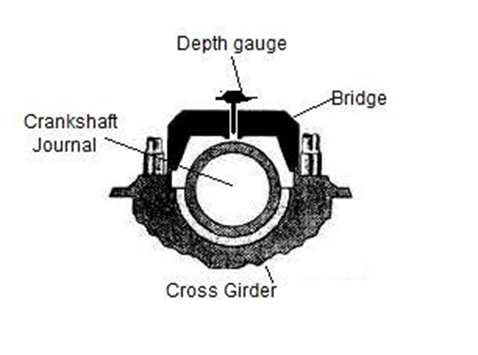
A simple vernier type depth gauge is then inserted in the hole provided on the bridge and the scale of depth gauge is rested on the crankshaft pin. The total depth on the scale is measured and compared with the previous reading and the reading in the manual for calculating the wear down of bearing.

In old model SULZER engines, a collar is provided in the bearing shell along with a small hole.  Thus, without removing the keep, the bridge is fitted adjacent to the keep and the depth gauge is used from the hole provided in the shell to measure the shell wear down.

2) Bridge With Feeler Gauge 

In some engines, after removing the shell and the keep, the bridge is installed on top. Also, in place of depth gauge, a feeler gauge is used to measure the clearance between the journal pin top and the bridge bottom. The bridge used here is different in terms of height and the gap between the pin and the bridge is very less

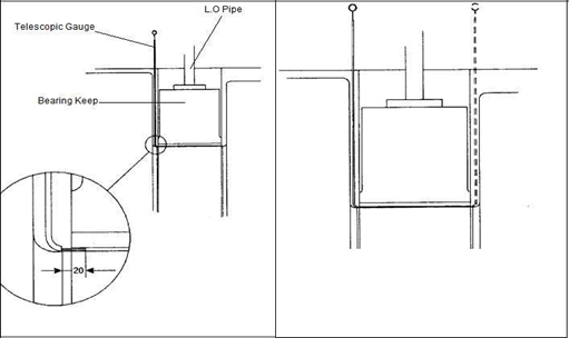
3) Telescopic or Swedish Feeler Gauge

In engines like MAN B&W, this is the most common method used to measure the bearing clearance of the top shell. In this method there is no need to remove any connection or keep for measuring the clearance.

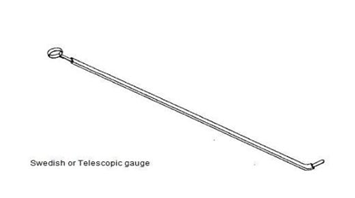
The telescopic gauge is inserted between the gap of the crank web and the bearing keep. When the tip reaches the shell top, the feeler is inserted between the shell and the pin to check the clearance.

4) Dial type Depth Gauge

This method is used in new MAN B&W engines (SMC-C) which does not require the top keep to be removed. The lube oil pipe connection screw hole is in the bearing keep which can be accessed from the hole on the bearing shell.

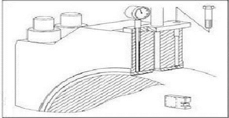
The dial gauge is inserted in this screw hole and the reading is taken as the clearance for upper shell.

5) Lead wire – The Traditional Method

This is a traditional method and to be used when no other alternative or tools are present. In this method, lead wire is inserted at different positions between bearing and pin. The bearing housing is tightened. Ensure not over squeezed the wire more than 1/3 rd of original diameter.

Testing holding down bolt

The classification societies requirement is that holding down bolts be checked by a surveyor, within each survey circle. this interval of time may be too long and the bolts should preferably be checked at six monthly intervals, unless there is a case history of the bolts going slack more frequently. Checking holding down bolts can be carried out on board the ship itself.

In new vessels, the bolts should be checked within one month of the commencement of the maiden voyage, or earlier if possible. The interval may then be gradually increased if all is found in order. After a vessel has been through bad weather, the bolts should be checked as soon as possible.

A rough method of checking holding bolts is the hammer test. Hold the tip of the thumb on one side of the nut face and strike the nut on the opposite side. If the nut is slack, the nut and stud spring against the thumb and then retract. the movement can be felt against the thumb. If a holding down bolt is of the fitted type, this test cannot be used, and a hydraulic jack must be used.

Holding down bolts tightness check:

.hdb tightness

factors that cause slackening of holding down bolts/ Faults of holding down bolt:

  1. Loose tie bolts
  2. Loose chocks
  3. shatter chocks
  4. Inadequate tightness of holding down bolts
  5. Bedplate or foundation plate deformation
  6. Unbalanced or overloading of engine
  7. Excessive vibration
  8. Ageing
  9. Collision or grounding
  10. Fire

Actions to be Taken for Slack Holding Down Bolts

When the chocks and their mating surfaces on the bed plate and tank top have fretted, the chocks cannot properly support the engine. If the holding down bolts are tightened, the crankshaft alignment may be seriously affected, with lesser effects being felt on cross head guide and cylinder alignment.

The seriousness of the situation will be depend on the amount of fretting that has occurred. Before any tightening of the holding down bolts is carried out, the alignment of the crankshaft should be checked, by taking deflections with a dial gauge. If the crankshaft alignment is satisfactory, the slack chocks can be removed and smoothed on the mating surfaces and replaced. The bolts can then be tightened to harden the chock. After all the walls and chocks have been tightened, the crankshaft alignment must be rechecked.

 why HDB are free through the bedplate, chocks & tank top:

  1. To avoid stress concentration on the bolts.
  2. To avoid the chances of fretting or notch effect this may cause fatigue failure.
  3. To transfer the tensile stress through the bolt from bedplate to tank top without concentration any particular parts.
  4. The bolt should be free to elongate otherwise they will lead to fatigue failure.

why HDB are long and made of high UTS steel

Holding down bolts are made long

  1. to increase fatigue strength modern engine use long elastic bolts.
  2. Because of greater length the bolts have greater elasticity hence less prone to crack

Bolts are made of high UTS steel because: TTFD

1) To increase tensile strength.

2) Have higher fatigue strength.

3) Have toughness property to sustain variable load without failure.

4) Have good ductile properties.

5) High UTS steel bolts can be tightened to a higher torque to reduce stresses.

6) Steel is resistant to corrosion.

Removal of broken tie bolts

.removal broken tie rod   .btr  .broken tie

Safety precaution:

  1. Permission must be granted to immobilize the engine
  2. Propeller clearance to be obtained
  3. Block start air mechanism and shut start air. main valve
  4. Turning gear engaged & indicator cock must be opened
  5. Stop L.O pumps and shut all V/V’s
  6. Crankcase should be treated as enclose space entry permit to work combined with a risk assignment should be done.

Procedure

  1. If breakage does occur, engine can be operated with reduced load for a limited period
  2. Position of fracture will dictate how broken pieces are removed.
  3. If bolt broken at mid length, lift out the top half, remove the bottom nut
  4. Feed a loop of braided wire cable (about 7mm diameter) down the tie bolt tube
  5. When it emerges at bottom a supporting piece can be fitted to the wire
  6. This enable broken tie bolt to be withdrawn.

Holding down bolt

.holding down bolt .hdb

Effect of operating an engine with loose tie bolts:

.lose tie rod  .ltr  .ltb

  1. Cylinder beam would flex and lift at location of slacken tie bolt.
  2. Rigidity of whole structure will be destroyed
  3. Noise & vibration will increase
  4. Other tie bolt will be overloaded leading to fatigue failure
  5. Machined mating surfaces will rub together and wear away … fretting
  6. Due to Fretting, Machined faces would eventually be destroyed.
  7. If fretting and tie bolts are tightened, cylinder to piston stroke alignment destroyed.
  8. If tie bolts are tightened on damaged face, bending moment is induced in tie bolts
  9. Misalignment between bedplate, frame and entablature
  10. Misalignment between xhead guide liner and stuffing box leading to excessive wear.
  11. Misalignment of main bearing and other sliding surface
  12. Transverse girders bend which could lead to cracking

The tie bolts are located close to the centre line of the engine

  1. The combustion forces acting on the cylinder head passes through the tie bolts
  2. As load increases tie bolt tend to pull transverse girders upward and load on bearing pockets tend to push downward. So the transverse girders are always subjected to a bending moment which is restricted by tie bolts
  3. As bending moment is the product of force & distance, the greater the distance, the greater would be the bending moment 
  4. So, to avoid excessive bending moment tie bolts are located as close to the centerline of the engine as possible.

Checking the pre-tensioning of tie bolt:

.tie rod tightness .tierod tightness .tiebolt tightness .tie bolt tightening

Tie bolt is tightened using hydraulic jack and bolts.

  1. Before commencing work Refer to manufacturer instruction for correct tightness values.
  2. Take crankshaft deflection
  3. Remove the thread protecting hoods from all tie rods and clean the contact face of the intermediate ring
  4. Mount pre-tensioning jacks on two tie rods placed opposite to each other, lower part of the jack rests on intermediate ring.
  5. Connect both pre-tensioning jacks to the high-pressure oil pump and vent the system
  6. Operate the pump until the pressure up to 600 bar and maintain same
  7. Check with feeler gauge, if there is any clearance between the tie rod upper nut and the intermediate ring.
  8. If any clearance exists, tighten the nut with tommy bar until it seats firmly on the intermediate ring and then release the pressure.
  9. If no clearance exists, the pressure can immediately be released.
  10. All the tie rods have to be checked in this manner in the sequence of (1-1),(2-2),(3-3),(4-4), (5-5), (6-6) as shown in fig. 

Correct method of fitting new tie bolts and pre-tensioning

.trt  .tie bolt tightening  .tbt

Initial preparation: 

  1. Permission must be granted to immobilize the engine
  2. Spare & tools must be checked
  3. Conduct tools box meeting
  4. Hydraulic jack or tools used must have valid calibration certificate
  5. Risk assessment with work permit to be done properly

Preliminarily work:

  1. Clean the tie rod properly and carefully before inserting into position
  2. The lower nut of the tie rod is screwed on.
  3. Clean the seating surface for intermediate ring and the upper nut.
  4. Place intermediate ring and screw upper nut on the tie rod.
  5. Fit the ring screw into the tie rod and lift carefully till the lower tie rod nut seats firmly.
  6. In this position tighten the upper tie rod nut with tommy bar until it is firmly seated on the intermediate ring.
  7. Separate lifting tackle from the rod and remove ring screw. 

Working sequences for tensioning:

  1. Measure distance ‘L’ for all tie rods and record them.
  2. Mount pre tensioning jack on the two tie rods place opposite to each other a/a, the lower part of the cylinder jack must rest on the intermediate ring.
  3. Connect both the jacks to high pressure oil pump and vent the system
  4. Operate pump until a pressure of 350 bar (1st stage ) is reached. Maintain the pressure while two upper nuts are tightened with tommy bar.
  5. Release the pump pressure to zero.
  6. In this manner tension all the tie rods in the sequences (1/1, 2/2, 3/3, 4/4, 5/5, 6/6) and measure all the distance ‘L’ and record them as ‘L1’
  7. Check maker’s reference value ‘L1’-‘L’
  8. Repeat the same procedure for final tightening to 600 bar (2nd stage)
  9. Finally measure the distance ‘L’ for each rod and record them as ‘L2’
  10. Check maker’s reference value ‘L2’-‘L’
  11. The values should be same if the tie rods are correctly tensioned.

TIE BOLTS

.tie rod .tie bolt  .tb

Purpose of tie bolt

  1. Hold bedplate, frames and entablature firmly together in compression
  2. Prevents fretting between these components
  3. Transmit the combustion gas load back to bedplate
  4. Maintain the alignment of the running gear
  5. Guide bush and pinching screws used to prevent excessive vibration
  6. Subjected to heavy tensile loads
  7. Prevent excessive bending moments in transverse girders

Performance of the engine:

Measure the Peak Pressure by Mechanical Peak Pressure Gauge:

This method is normally applied in 4 stroke generator engines where a peak pressure gauge is used for individual cylinder and pressure generated during combustion is noted. With the same gauge, the compression pressure of the cylinder is also measured when the unit is not firing. The variation in the peak pressures generated is then taken into account for drawing out faulty units, adjusting fuel racks and overhauling combustion chamber parts in order to achieve efficient combustion.

Indicator Card Measurement:

This is another mechanical method to measure the performance of engine cylinders by applying indicator drum and plotting graph on cards. Two types of cards are used for this purpose-power card and draw card. With the help of these two diagrams, we can determine the compression pressure, peak pressure and engine power.

Digital Pressure Monitoring by DPI:

Digital pressure indicator is an electronic mode to monitor the power and performance of the engine. With the help of DPI, the variation in the cylinder performance can be plotted and interpreted in graphical form and corrective action can be taken.

Intelligent Combustion Monitoring (ICM):

The new generation engines are continuously monitored by ICM, which measures the real time in-cylinder pressure in all engine cylinders. This package offers a broad range of data processing tools for evaluating performance and for helping to determine engine malfunctions (extensive blow by, exhaust valve operation, fuel injection etc.).

Monitoring of Engine Control Parameters: 

The engine control parameters like fuel injection timing, exhaust valve timing, variable turbocharger vane opening angles, lambda control etc. are monitored and any variation is set to achieve the best possible efficient combustion.

Engine Parameters: 

The engine parameters are the best source for finding out any fault or variation in the engine performance. Variation in temperature, pressure and power produced by each cylinder must be frequently monitored and adjustment must be done accordingly to achieve efficient combustion.

Logbook Monitoring: 

This is the most basic but commonly ignored method for monitoring engine performance. The log book record for engine room machinery is kept onboard for years on ship. The log book of current month and of previous months must be compared for recorded parameters, which will give the exact variation of engine parameters. If the variation figure is more, engine controls, parameters and parts to be adjusted/ overhauled.

Engine Emission:

 The marine engine releases exhaust smoke as waste product after the combustion. The color and nature of the exhaust should be monitored continuously, and engineers must know which exhaust trunk discharge is dedicated for which engine. The change in exhaust smoke is a prominent indication of problem in the combustion chamber.

Colors of Smoke

The color of the smoke tells about the condition of the machines. The ideal color of the smoke should be transparent to slight grey.

  • A white color indicates presence of water vapor in fuel.
  • Blue colored smoke indicates the presence of lubricating oil in the smoke.
  • Dark black color indicates inefficient combustion or the lack of air. It could also be due to scavenge fire or economizer fire or boiler problems.

Exhaust valve

.exh valve

Material for exhaust valve:

The valve housing is of cast iron and arranged for water cooling. The housing is provided with a bottom piece of steel. The spindle or valve stem is made of heat resistant steel with stellite welded on to the seat.

Stellite is a range of cobalt-chromium alloys designed for wear resistance. The alloys may also contain tungsten or molybdenum and a small, but important, amount of carbon.

Cause of Exhaust Valve Burning : Exh vv burning

.exhaust valve burning

.exh v/v burning .exh vv burning  .exhv

CAUSES:

  1. Continuous overloading of Engine or particular unit. 
  2. Poor combustion (or after burning) of fuel due to dirty fuel injectors, incorrect fuel injection pressure, incorrect fuel temperature, late fuel injection timing, Air starvation, water, or impurities in fuel. 
  3. Cold Corrosion (Cooling water temp low) & Hot Corrosion (due to bad quality of fuel),  
  4. Incorrect fuel valve spray angle 
  5. Insufficient cooling water supply may cause valve to overheat. 
  6. Valve not close properly due to Incorrect Tappet Clearance. 
  7. Ineffective seal between valve & valve seat. (v/v leakage)
  8. Carbon buildup in the valve seat. 
  9. Unsuitable materials used. 
  10. Valve spindle not rotating. 
  11. Running a dry fuel such as L.P.G resulting in inadequate lubrication of the valve seat. 

Indication of Exhaust valve Leaking: 

  1. Low Pcom and Low Pmax 
  2. High Exhaust temperature 
  3. Scavenge Air or Supercharging air pressure will decrease
  4.  Noise. 
  5. Smoky Operation. 
  6. Abnormal light spring diagram showing pressure dropping down. 

Exhaust valve maintenance and clearance checking

  1. Use template and filler gauge to measure the wear down the valve seat
  2. Use template and filler gauge to measure the bottom piece wear. If wear is beyond the highest limit then replace the bottom piece
  3. Replace all the o ring for bottom piece
  4. Grind the outer seat of the bottom piece with carborundum and special grinding tool
  5. Use vernier calliper to measure the thickness of the spindle and calculate the wear down.
  6. Inspect and measure the wear down of the guide bushing at top and bottom by using dial gauge. If wear is beyond the highest limit, then replace the guide bushing
  7. Replace all the o ring in the guide bushing
  8. Pressure test the air cylinder relief valve
  9. Air cylinder piston o ring and Teflon ring replace if necessary
  10. Measure the wear down of the oil cylinder piston ring.
  11. Measure the wear down of the oil cylinder liner
  12. Replace the o ring inside oil cylinder

Inspection of liner:

.liner inspection   .li

Preparation: 

  1. Permission to be granted to immobilize the engine
  2. Propeller clearance to be obtained
  3. Block starting air mechanism
  4. Engage turning gear, open indicator cocks
  5. Stop necessary p/p’s and v/v’s
  6. Drain water and shut all v/v’s
  7. Permit to work with risk assessment carefully done
  8. Tool box meeting to be carried out
  9. All tools must be arranged before the inspection
  10. Remove the cylinder head

Safety precaution:

i.  Ladder should be properly hung

ii.  Safety harness must be worn

iii.  Adequate lighting must be arranged

iv.  Nothing should be hanging from overhead crane.

Inspection procedure:  

With piston removed, or bring the piston to BDC for liner inspection

Special attention to be given to check for:

  1. Check the surface of gasket sitting area
  2.  Ridge formation at TDC position
  3. Flow of oil from lubrication ports
  4. Cracks and damage at lubrication openings
  5. Clover leafing – corrosive wear between the lubricator ports if the cylinder oil cannot neutralize the acid products of combustion
  6. Mechanical friction wear marks and abrasive wear on the liner surface
  7. Dark areas of liner indicating blow-by
  8. Corrosion in liner surface – Acidic and cold corrosion
  9. Scuffing and scoring marks of liner surface
  10. Glazing of liner surface (mirror finish)
  11. Cracks on the surface and near scavenge port openings
  12. Sharp edgy surface of scavenge ports
  13. Liner calibration to check the liner ovality and wear 
  14. If it exceeds the limit, the liner should be renewed. for slow speed maximum allowable wear is 0.8-1% of the bore. 
  15. For medium speed engine maximum 0.7% of the bore

Discuss the ideal location of lubricating quill on a liner

  1. Not near port areas oil can be scraped and blown away
  2. Not near high temperature zone or the oil will burn easily
  3. Should be located in such area points to ensure even and complete coverage as possible

In between piston rings (1st &2nd) with the piston at TDC, piston ring will spread oil effectively.

Clover Leafing:

.clover leafing

Clover leafing is a form of wear on cylinder liners due to high sulphur content in the fuel oil and when the supply of lube oil is not uniform around the radial bore of the liner.. Clover leafing takes place between each pair of lubricating quills

  • Alkaline cylinder oil is used to neutralize acid. 
  •  Perfect distribution of cylinder oil is difficult.
  • Surfaces get either more alkalinity or less depending on the position of cylinder lubricator quill & TBN used.

If TBN use is more:

  • Surfaces near quills will get excessive alkalinity leading to hard calcium compounds formed.
  • Alkaline compounds are burnt and formed hard deposits which caused abrasive wear.
  • Surfaces far from quills will have alkali neutralized and thus minimum wear is experienced.

If TBN use is less:

  • Surfaces near quills will have minimum wear but surfaces far from quills will be starved of alkaline compounds 
  • This will lead to acidic corrosion and thus experienced maximum wear ,

This above phenomenon known as clover leafing which can result in blow past and ultimate failure of liner in severe case

Causes of excessive wear:

  • Improper running in
  • Overloading of engine – overheated and lube oil film breakdown
  • Use of low Sulphur fuel (less than 1% Sulphur) in conjunction with high alkaline cylinder oil and vice- versa
  • Inefficient combustion -carbon deposits
  • Increased piston ring clearance and bad ring profile
  • Inadequate lube oil supply
  • Lube oil too low in viscosity/ TBN
  • Contamination of lube oil by abrasive material (In 4 stroke engines)
  • Cylinder liner material unstable –phosphorous/silicon
  • Cylinder wall temperature too high or too low – oil film breakdown or corrosive wear.
  • Scavenge air temperature too low –corrosive wear
  • irregular draining of charge air cooler/ water in the scavenge air

Liner

.liner

.liner material

Material

The cylinder liner is manufactured from Pearlitic Grey cast iron (Ni, Cr, Mo) alloyed with vanadium, titanium and molybdenum. Grey cast iron contains graphite which itself is a decent lubricant and the alloying elements of Grey cast iron help in resisting corrosion and improve its wear resistance at elevated temperatures.

Property:

  • It should have adequate strength and fatigue life
  • Good heat transfer capacity
  • Porosity to retain lubrication (honing)

Wear rate

.liner wear rate .wear rate

It is obtained by measuring diameter increased per thousand running hours. Thus:

•          Wear rate since last recorded measurement

= (Increase in diameter since last record/ Running hours since last record) X 1 000

= mm/10 00 hrs

•          Wear rate since new

= (Total increase in diameter/ Total running hours since new) X 1 000

= mm/10 00 hrs

•          Wear rates vary, but as a general rule, for a large bore engine a wear rate of 0 .05-0 .1mm/1 000 hours is acceptable.

•          Liner should be replaced as the wear approaches 0 .8-1% of liner diameter.

•          Liner is gauged at regular intervals.

•          The wear rate for a medium speed liner should be below 0 .015mm/10 00hrs.

Causes of excessive wear: 

.liner wear .liner excessive wear

1.         Improper running in – improper smoothing and geometry will increase wear rate.

2.         Misalignment of piston

3.         Incorrect piston ring clearances

4.         distortion of cylinder – thermal stress and uneven tightening

5.         Unstable cylinder liner material – phosphorous / silicon

6.         Cylinder wall temperature too high or too low – oil film breakdown or corrosive wear

7.         Scavenge air temperature too low, causes water condensation– wash oil film, form acid, rusting

8.         Inadequate oil supply or unsatisfactory oil supply

9.         Lube oil too low in viscosity or too low in alkalinity

10.       Contamination of lube oil by extraneous abrasive material – 4stroke engine

11.       Overloading of engine – overheated, distorted and lube oil destroyed

12.       Inefficient combustion – carbon deposit

13.       Use of low sulphur fuel (less than 1% sulphur) in conjunction with high alkaline cylinder oil and vice versa

Main engine unit survey and documents

.me survey .me unit survey .main engine survey

1. Planning

  • Check the survey list of machinery
  • Get exact date of survey and get immobilization and inform office
  • Check previous record of maintenance
  • Check and prepare all necessary spares and tools
  • Check all lifting gear
  • Check hydraulic pump, jacks, high pressure hose condition
  • Ensure enough manpower and time available in port
  • Read manual for special instruction and data.
  • Carry out briefing for everyone involve, precaution, work to be done, and time available
  • Carry out risk assessment

    2. Tools

    Prepare tools.                        

    1. Piston and cylinder head
      • Hydraulic pump, hoses and hydraulic jacks
      • Piston lifting tool and cylinder head lifting tool
      • Piston inserting tool
      • Stuffing box spacer
      • Piston and cylinder head stand
      • Piston ring expander
      • Piston crown wear measuring template

    2. Liner

    • Liner lifting tool and liner support beam.
    • Liner jack and jack support
    • Liner calibration gauge
    • Liner inspection ladder
    • Stuffing box area covering plate

            3. Chain blocks

    • Check its safe load carrying capacity
      • Check chain link condition
      • Check free movement of chain in both direction
      • Check safety lock for proper condition on hanging hook.
      • Check condition of hook for sign of crack or damage

     4. Eye bolts, shackles, wire sling and safety belt

    • Check for safe load carrying capacity
      • Check overall condition for any damage
      • Check thread condition of eye and shackles

    3. Safety during crane operation

    • Don’t operate when ship is incline
      • Don’t press button simultaneously
      • Do not bypass limit switch
      • Do not operate if someone under or on the way
      • When 2 person directing, do not operate

    4. After arriving port

    • Once finished with engine, get immobilization permission
    • Propeller clearance to be obtain form bridge
    • Shut starting air system and hang notice not to start main engine
    • Drain the air line, keep open
    • Open indicating Cock
    • Engage turning gear and turn ME with manual cylinder lubrication
    • After half an hour stop LO pump
    • Give time to cool engine
    • Open crankcase door, lock on open position and give ventilation !
    •  Isolate jcw inlet and outlet valve for particular unit and drain.
    • Isolate fuel inlet and return valve for particular unit.
    • Exhaust valve spring air to isolate
    • After ventilation of crankcase check, atmosphere check for oxygen content, explosive gas and toxic gas
    • Enclose space entry permit to complete
    • No naked light inside crankcase
    • Proper lighting to be ensure inside crankcase

    5. Removal of connection

    • with removal of following
    • Remove exhaust bellow
    • JCW outlet pipe before the valve
    • Exhaust valve spring air connection
    • Hydraulic actuator high pressure pipe
    • Fuel injector high pressure pipe and connection
    • Starting air valve connections

    6. Removal of cylinder head

    • Fit hydraulic jack on all cylinder head nuts and connect high pressure hose.
    • Open jack vent and start to pump slowly
    • Once air bubbles are removed, shut vent and stop pumping
    • Ensure all jack vents are shut then pump to recommended pressure and stop pump
    • Use tommy bar to loose nut
    • Ensure all nuts are loose
    • Release pressure, remove jacks and remove nuts
    • Fit cylinder head lifting tool
    • Lift slowly the cylinder head using ER crane
    • Care to be taken when lifting, to make sure it does not come in contact with other cylinder head.
    • Place the cylinder head on cylinder head stand

    7. Removal of piston

    • After proper ventilation of crankcase, remove the lashing of all secure bolts and remove require pipe connection
    • Turn the piston to BDC and remove piston nut and lock device
    • Fit the stuffing box spacer on piston rod palm
    • Remove stuffing box securing bolts and its locking device
    • Remove cylinder head metal gasket
    • Clean liner surface of deposits at combustion area so as piston does not get stuck during extraction.
    • Turn the piston towards TDC, carefully keeping eye on turning gear ampere
    • Clean the lifting holes on crown
    • Fit piston lifting tool, ensure all bolt secured
    • Ensure crane is in mid-position and ship is even keel
    • Slowly lift up piston ensure stuffing box spacer does not get in contact with diaphragm.
    • Continue to lift, ensure piston is not swinging causing piston palm get in contact with liner
    • Once out, lower the piston on its stand and put cover on stuffing box housing. !
    •  Remove the lifting tool

    8. Inspect and cleaning

    Cylinder head

    • Before cleaning,
      • check for carbon deposit.
      • Any trace of water leakage.
    • After cleaning,
      • crack test to be carried out at change of section (around injector bore, exh valve bore area, indicating cock, starting air valve, relief valve)
      • Pressure test cylinder head cooling space
      • Keep ready for survey

    Piston crown

    • Check for burning at the top
    • Use template to check wear
    • Check for crack on top

    Piston and piston ring

    • before cleaning check for carbon deposit amount and condition
    • check ring condition for sticky, broken, cracks
    • after taking out, carry out thorough cleaning
    • check for free movement
    • check ring clearance and groove clearance

    Piston skirt and side wall

    • Check for any rubbing mark

    Cooling passage

    • Scaling due to poor water treatment
    • Cracking due to high temperature
    • Pressure test as per manual
    • Take photo for before after for future reference
    • Keep ready

    Piston rod and stuffing box

    • Piston rod diameter to check at different point in manual
    • Record and compare previous record
    • Carry out crack test at change of section of piston rod
    • Check for any scratch mark
    • Overhaul stuffing box, clean all parts, and check clearance of rings.
    • Take photograph

    Cylinder liner

    • Check for dryness and oiliness, clover leafing, hard particle mark, polishing
    • Check if scavenge port is choke & inspect
    • Check for carbon deposit at top of combustion area
    • Calibration to be check and recorded and compare with previous record !
    • Check the lubrication points for cylinder lub oil flow by pumping manually !
    • After cleaning, crack test to carry out around port edge.

    9. Inspection of surveyor

    • After cleaning and decarbonizing, all parts to be kept ready for survey. !
    • Overhaul stuffing box with rings renewal as required box back !
    • All joints, gasket and seal rings renewed and kept ready.
    • All calibration and measurement record are recorded and kept ready for surveyor
    • Overhauled exhaust valve and fuel injector ready for box up after completion of survey
    • After survey, all parts box up as per manual and system to be put in running order, take all precautions. Check for leakage and rectify accordingly.

    Piston material

    .piston material

    • Crown is made up of heat resistant forged steel alloy including chromium, nickel and molybdenum for heat and corrosion resistance without compromising on strength
    • Skirt is made up of nodular cast iron or forged silicon aluminium alloy which has the advantage of being light, with low inertia, reducing bearing loading.

    M/E Alarms, safeties, trip

    .me alarms and safety trips .me safety

    Different Engine Slow Down Situations

    In this situation the main engine will come to dead slow RPM i.e. below 30 RPM as the slow down protection gets activated. Following are different slow down situation for main engine:

    • Lube oil pressure falls to 1.5 bar
    • Cam shaft pressure falls below 2 bar
    • Control air pressure is low < 5.5 bar
    • There is no flow of piston cooling media (water or oil)
    • Oil mist detector or Main bearing sensors has been activated
    • Lube oil temperature at the inlet of engine is high > 60 deg C
    • Piston Cooling temperature is  high > 75 deg C
    • Jacket water Temperature is high > 88 deg c
    • Engine cylinder exhaust temperature is high > 450 deg C
    • Scavenge air temperature is high > 65 deg C
    • Thrust block temperature is high > 75 deg C
    • Low flow of Cylinder lube oil

    Different Shut down Situations

    • Lube oil inlet pressure to engine is very low <1 bar
    • Cam shaft Lube oil pressure is very low < 1.5 bar
    • Low Jacket cooling water pressure < 0.1 bar
    • Lube oil inlet pressure for turbocharger is low < 0.8 bar
    • Very high Jacket cooling water temperature >95 deg C
    • No flow of Cylinder lube oil
    • Thrust block temperature very high > 90 deg C
    • Over speed of the engine which activates shut down at 107 % of Max. continuous rating MCR

    Different Starting Interlocks are

    • Turning gear engage interlock
    • Auxiliary blower off interlock
    • Lube oil and other important pump not running interlock
    • Running Direction Interlock

    Safety Devices

    1. > Crank case relief door
    2. > Scavenge space relief door
    3. > Cylinder head relief valve
    4. > Starting air relief valve
    5. > Starting airline flame trap
    6. > Oil mist detector
    7. > Rotation direction interlock
    8. > Turning gear interlock

    Surging:

    .surging   .tcs  .turbocharger surging

    .tc surging

    1. Surging is a phenomenon that affects centrifugal compressor when:
      1. mass flow rate of air falls below a suitable level at a given pressure ratio.
    2. Surging is cyclic back flow of air into compressor when there is high resistance to air flow
    3. It is caused due to periodical breakdown of air delivery from blower

    Indications of surging:

    1. Rapid surge in scavenge air pressure
    2. Howling Noise
    3. Alternate Suck-in & push-out at blower intake
    4. Gulping of air by blower
    5. Repeated irregular violent thud by blower
    6. Fluctuating T/C RPM
    7. Fluctuating Engine RPM
    8. High Exhaust Temperature
    9. Black Smoke

    Causes of surging:

    1. Insufficient Engine room ventilation
    2. Dirty air filter
    3. Clogging of TC intake silencer
    4. Dirty blower
    5. Dirty scavenge air cooler
    6. Clogging of gas inlet protection grid
    7. Dirty nozzle ring/turbine
    8. Wear of TC components (nozzle ring, turbine blades, shroud ring)
    9. Increased back pressure due to dirty EGE/silencer
    10. Power imbalance between cylinders
    11. Unit cut-out & engine running above 40-50% load
    12. Engine racing
    13. Hull fouling – causing the engine to run at overload
    14. Faulty injection/misfiring
    15. Mismatching engine & T/C

    Consequences of surging:

    1. Vibration
    2. Bearing damage
    3. Turbine blade damage
    4. Rotor damage

    Minimizing the possibility of surging: 

    1. Keep the turbocharger intake filter clean.
    2. Grit -wash the turbine and water wash the compressor side of the turbocharger.
    3. Efficient maintenance of air-cooling system
    4. Proper maintenance and checks should be done for different turbocharger parts periodically. If there are any issues, turbocharger repair to be done as soon as possible without loading the engine
    5. Soot blow should be done from time to time in case of economizer or exhaust boiler
    6. Indicator cards to be taken to assess the cylinder and power distribution of individual units
    7. Ensure the engine auxiliaries and parts which affect the turbocharger are maintained properly
    8. Regular cleaning and inspection of the exhaust manifold

    Types of turbines:

    .turbine types  .impulse   .types of turbine     Draw copt    .copt

    Working principle

    In the impulse turbine the entire pressure drop of the stage is across the fixed blades which act as nozzles. These nozzles accelerate the steam to a high velocity. This high velocity steam impinges upon the moving blades and drives them at a certain velocity. Within the moving blades the steam is turned to transfer of energy and leaves at a low velocity

    In the reaction turbine the stage pressure drop is spread across both the fixed and moving blades. The fixed blades act as nozzles and accelerate the steam to a moderate velocity due to the partial pressure drop. This steam then impinges upon the moving blades and imparts some energy to them. Within the moving blades the steam is turned and accelerated by the remainder of the pressure drop.

    S/noImpulse TurbineReaction Turbine
    1It consists of nozzles and moving bladesIt consists of fixed blades (stators) and moving blades
    2Pressure drop occurs in nozzles and constant across moving bladesPressure drop occurs across fixed as well as moving blades
    3Steam strikes the blades with kinetic energySteam strikes the blades with kinetis and pressure energy
    4It has constant blade channel area; blades are identical for various stagesIt has varying blade channel area and blade sizes different for various stages
    5Due to higher pressure drop per blade, the number of stages required is lessDue to lesser pressure drop per blade, the number of stages required is more
    6Occupies less spaceOccupies more space
    7Less power developedMore power developed
    8Low efficiencyHigh efficiency
    9Partial admission of steam possible to control output powerPartial admission of steam not possible
    10Suitable for marine applicationsSuitable for industrial power generators
     

    The reaction effect caused by this accelerating steam imparts more energy to the moving blades. The steam leaves the stage at a low velocity relative to the next row of fixed blades. This is illustrated in Figure 3 for impulse blading and Figure 4 for reaction blading. Figure 4: Reaction turbine blading and conditions Figure 3 shows, at the top, the end view of four stages of fixed and moving blades of an impulse turbine and, at the bottom, the pressure and velocity profiles over these four stages. Since the energy in the steam is represented by the pressure (heat energy) and velocity (kinetic energy), the conversion and transfer of energy in the blading can be visualized. Initially the pressure is high representing a high energy level. In passing through the first row of fixed blades some potential energy is converted into kinetic energy as indicated by the slight drop in pressure and increase in velocity. In passing through the mating row of moving blades the kinetic energy is transferred to the rotating wheel of the turbine as indicated by the drop in velocity. There is no change in pressure in the moving blades. It is evident that, at the exit from this first stage, the steam has given up part of its initial energy and transferred this to the rotating parts of the turbine. A similar process is repeated in the remaining three stages. Additional stages may be added to extract any remaining energy of the steam. Figure 4 shows a similar representation of four stages of fixed and moving blades of a reaction turbine given similar boundary conditions. As before, the pressure is initially high representing a high level of energy. In passing through the first row of fixed UNESCO – EOLSS SAMPLE CHAPTERS THERMAL POWER PLANTS– Vol. III – Steam Turbine Impulse and Reaction Blading – R.A. Chaplin ©Encyclopedia of Life Support Systems (EOLSS) blades some potential energy is converted into kinetic energy but not as much as in the impulse turbine. There is less of a drop in pressure and consequently a smaller increase in velocity. In passing through the mating row of moving blades there is a further drop in pressure as well as a drop in velocity. Thus the transfer of energy is in two parts, namely the transfer of kinetic energy of the steam and the transfer of some of the potential energy of the steam to the moving blades. The net result at the exit from this stage is a low velocity and a pressure somewhat lower than the initial pressure. A similar process is repeated in the remaining three stages. Any number of stages may be added to obtain the desired pressure drop across the turbine. The main difference between the impulse turbine and the reaction turbine is that, in the former, there is a pressure drop across the fixed blades only, whereas in the latter, there is a pressure drop across both the fixed and the moving blades. For similar boundary conditions this results in a lower velocity of the steam leaving the fixed blades in the case of the reaction turbine. This velocity leaving the fixed blades is relative to the fixed components and is therefore described as the absolute velocity. The velocity associated with the moving blades is known as the relative velocity (relative to the moving blades). In reaction blading the increase in velocity in the moving blades is achieved by blades designed to act as nozzles to convert some pressure energy in the steam into kinetic energy. The change in flow area in the blades governs the increase in velocity. From the continuity equation it is evident that, for small changes in density, a reduced flow area will result in an increase in velocity. The shape of the fixed blades in both impulse and reaction turbines is such as to reduce the flow area and increase the velocity. The shape of the moving blades however is not the same for impulse and reaction turbines. The moving blades of impulse turbines do not have a change in flow area. They do not therefore change the velocity of the steam but only change its direction. The moving blades of reaction turbines do have a change in flow area. They are shaped like nozzles and act to accelerate the steam as it passes through them. They also change its direction. The difference in the moving blades is evident from Figure 3 and Figure 4. In an impulse turbine the blades are symmetrical about the plane of the turbine wheel carrying the blades whereas in a reaction turbine they are not. Figure 5 and Figure 6 clarify the concept of flow areas and blade symmetry. The difference between the two is easily seen when viewing the blades from the end. In the latter figure the reduction in flow area and consequent increase in velocity is clearly evident. On an actual turbine rotor however the blades invariably have circumferential shrouding over the tips and the blade profile cannot be seen.

    Turbocharger

    .turbocharger   .tc

    turbocharger washing in blower side and turbine side

    Blower side water washing

    1. It can be done when M/E on full load.
    2. Fill up the warm fresh water to hopper and closed the cover.
    3. Open the valve and water will flow into the blower casing and mechanically attack the blower blades and clean the deposit.
    4. Close the valve, open the cover and check the cleaning water must be empty.

    Turbine side water washing procedure

    1. Turbine side water washing can be made with hot fresh water.
    2. Inform to the bridge
    3. Reduce the M/E rpm to recommended speed and hence turbocharger rpm.
    4. Check the water washing injection nozzle if fitted. (directly aim to the exhaust grips before entering to the turbocharger)
    5. Open turbocharger drain valve.
    6. Open the water supply about 1 bar to turbine side.
    7. Water washing must be made until the clean water comes out.
    8. Close the water supply and remove the nozzle.
    9. Exhaust side drain can be closed after all water is drained out and dried.
    10. Inform to the bridge and increase the M/E rpm gradually to sea speed.
    11. The turbine side water washing is usually at departure after manoeuvring time.
    12. For usual practice cleaning is done at every 500 hr, running hour depending on the cleanliness of the turbocharger .

    Grit Washing or Dry Cleaning of Turbocharger

    1. Turbine side cleaning is superseded by walnut shell, with grain size of 12 to 34 mesh 
    2. No speed reduction required and cleaning can be done at full speed, once every day
    3. Compressed air of (3 -5 bar) is used to help the grains strike the deposited Turbine Blades and Nozzles, giving effective cleaning of hard particles
    4. Air supply pipe is fitted to solid grain container, and grains are injected into exhaust system by air pressure, at the same point (as in water washing) just after exhaust grids
    5. Turbine casing drain kept open during cleaning time (about 2 minutes only) 

    Aux Blower Tripped During Maneuvering:

    •  Check Circuit Breaker if trip
    •  Check fuses if not blown
    •  Check motor temp if not overloaded, any burning smell
    •  Remove end cover of motor & turn cooling fan for smooth turning else bearing jammed or impeller touching
    •  Check Motor insulation, meggar, continuity test
    • Check pressure switch for cut in/out might malfunction
    •  If one motor burned than can proceed with reduced RPM. If both motor burned than command rpm will not come & dense black smoke will be emitted. In such case abort berthing.

    Reflex type gauge glass:

    .reflex

    Article link: http://www.altonashop.com/Products/reflex_glass_level_gauges.htm

    Working principle:

    Reflex level gauges working principle is based on the light refraction and reflection laws.

    Reflex level gauges use glasses having the face fitted towards  the chamber shaped to have prismatic grooves with section angle of 90°. When in operation, the chamber is filled with liquid in the lower zone and  gases or vapors in the upper zone; the liquid level is distinguished by  different brightness of the glass in the liquid and in the gas/vapor zone. The reflex level gauges do not need a specific illumination: the day environmental light is enough. Only during the night an artificial light must be provided.

    The different brightness in the two zones is obtained as explained below:

    Liquid Zone:

    This zone appears quite dark when the gauge is in operation and lighted as above said.

    Given the construction, most of the environmental light rays incident on the external face of the glass are quite perpendicular to said face and, therefore, not deviated by the glass. These rays reach the glass/liquid interface with an inclination of approx. 45°. The critical angle glass/liquid is always superior to 45°. Therefore, the ray’s incident within the critical angle (practically the totality) are refracted within the liquid and, since the internal walls of the gauge chamber are not reflecting, the rays cannot be seen from the outside. In fact, the zone will appear dark, nearly black, to the observer.

    Gas/vapor Zone:

    This zone appears almost silver bright to the observer. As for the liquid zone, the light rays reach the glass/gas-vapor interface with an angle around 45°. Since this angle is greater than glass/gas-vapor critical angle, the rays are not refracted, but totally reflected making 90° turn, thus reaching the nearest glass/gas-vapor interface again with angle of 45°. For same reason they will be reflected and turned by 90° towards the observer, to whom the zone will

    Differential pressure transmitter:

    Article link: https://instrumentationtools.com/differential-pressure-transmitter-working-principle/

    Question:

    Q. Local gauge glass normal but remote level gauge showing high level, cause?

    Possible Reasons:

    • Leaky bypass valve (pressure regulating valve)
    • Defective primary element (primary sensing element-diaphragm)
    • Defective transducer

    Q. How to blow down DP cell sensing lines?

    1. Close low pressure sensing line valve.
    2. Close high pressure sensing line.
    3. Open bypass valve connecting L.P and H.P side.
    4. System ready for blowdown.
    5. Open low pressure side blowdown valve, wait for about 10 seconds, then close it.
    6. Open H.P side blowdown valve, wait for about 10 seconds, then close it.

    Q. Boiler tube plugging:

    .btp  .boiler tube pluging

    Procedure:
    • Identify the defective tube when the boiler is pressurized, burner cut out.
    • Take permission from office.
    • Shut down boiler according to instruction manual, let it cool down, ventilate before entering.
    • Whole process may take 2/3 days depending on the severity of tube failure. Take preparation accordingly.
    • Prepare enclosed space entry permit, read, and understood by working personnel, have It signed by master.
    • Boiler is provided properly sized tube blanks, use them to blank off the tubes.
    • Tube needs to be blanked off on both end, clean tube ends.
    • Insert tube blanks by hammer, weld if necessary.
    • Fill up boiler with feed water and check for leakages under pressure.
    • Fire up boiler slowly according to instruction manual.

    Control:

    Boiler Auto combustion Control:

    .acc  .bacc

    MV= manipulated value (set point, process value difference)
    PV=process value (measured value)
    A/H=auto or hand
    Description:

    Initially, MV=SV, PV1=C.SP1, PV2=CSP2, a ≈ b, c ≈ d.
    If steam demand ↑, MV↓
    O/P of R/A Master Controller ↑, c↑ , a↑
    c > d, d passes through LSS,
    so no change in CSP1,
    But a > b, ‘a’ passes through HSS,
    CSP2↑, PV2↓ wrt CSP2
    O/P of D/A Air flow controller ↓
    ATC air damper opens more,
    Combustion Air flow ↑, d↑,
    d passes through LSS since d < c,
    CSP1 ↑, PV1↓ wrt CSP1,
    O/P of R/A Oil flow Controller ↑,
    ATO oil control valve opens more,
    Steam pressure restored to SV within a few cycles due to I-action of the Master controller. The control scheme above ensures that air is increased ahead of fuel to prevent fuel-rich condition when load ↑. And similarly, fuel will be decreased ahead of air to prevent fuel-rich condition when load ↓