.corrosion
Corrosion is the deterioration of a material because of its interaction with its surroundings
Hot Corrosion:
It occurs due to the presence of Vanadium (Va) and Sodium (Na) in the fuel oil and affects exhaust passage of the engine. Creates a molten paste at temperatures more than 450 degrees and stick to the exhaust valve.
Cold corrosion:
It occurs due to the presence of sulphur in fuel oil and affects the cylinder liner and other parts of combustion chamber
Hot Corrosion process:
Vanadium is a naturally occurring element in marine fuel oils in soluble form, which means, it will not be separated even when the fuel is treated in the centrifuge. Vanadium, when combined with Sodium, can cause damage to the engine under elevated temperature. Sodium and Vanadium compounds are formed at a high temperature, which plays a crucial role in hot corrosion.
The availability of abundant oxygen in the combustion chamber during the burning of fuel results in the oxidation of vanadium to form VO and VO2. During the temperature drop in the further combustion process, VO2 undergoes further oxidation resulting V2O5.
V2O5 has a low melting point and becomes semi-liquid, sticky in nature and adhere to the surface they come into contact with.
Sodium in the fuel reacts with water vapour during combustion to generate NaOH. This, in turn, combines with SO2 forming sodium sulphate.
Sodium sulphate condenses at a temperature approx. below 890 deg. C and will adhere to surfaces with already present V2O5. This resultant deposits block gas passages and corrode metal surfaces. If the ratio of Va:Na is 3:1, the resulting complex melting point is at it’s lowest, which is about 350 – 450 deg C, and there is an increased likelihood of deposit formation.
Fuels with high vanadium and sodium will increase the tendency for deposit formation in the exhaust passages. At higher temperature (>600 deg C), ash deposits can accelerate corrosion of metals and fouling of gas passages.
Effect of Hot Corrosion
1. Erosion: It mainly takes place along the exhaust gas passages, as ash and carbon deposits from high-temperature exhaust gases wear metals. Because of this, the exhaust valve is profoundly affected.
2. Fused salt corrosion: At high temperature, Na and Va form corrosive fluxes, attacking and corroding exhaust valves, turbocharger nozzles and blades. The salts dissolve the protective oxide layers, facilitating further gas phase oxidation.
3. Gas phase oxidation: It is the effect of oxygen on metal engine surfaces in the hot exhaust.
How to control hot corrosion?
• Maintain exhaust temperature well below melting point of Na and Va complex (about 400c)
• Use of Sterlite coating or Nimonic steels on exhaust valve seat for protection from corrosion
• Use exhaust valve rotators to smoothen radial temperature distribution and to prevent repeated impact damage at a single point on the valve face
• Fuel additives like ash modifiers can be used which can modify and increase the melting point temperature of Na and Va complex formed when the ash is not in a molten form and not corrosive
• Controlling fouling of exhaust passages and machinery, i.e. regular cleaning and inspection of the exhaust manifold, frequent water washing of turbocharger, overhauling of the exhaust valve, etc.
COLD CORROSION procedure
Sulphur is another element which is a naturally found in crude oil. Its level is indicated by the content of sulphur found in the residual fuel stream obtained during the process of crude oil refining.
Sulphur in the fuel acts as a natural EP (Extreme Pressure) additive, providing inherent lubricity in the fuel passing through the injectors and pumps.
With plenty of oxygen available in the combustion chamber, the Sulphur is converted to SO2 and it further combines with oxygen to form SO3 Sulphur trioxide.
When SO3 comes in contact with water or water vapour present in the scavenge air, it will react and form H2SO4.
If the engine is running inefficiently at low RPM, the liner temperature is on the lower side and below the dew point of sulphuric acid and water (120-160 deg C). Corrosive mixtures will condense on the linear walls causing cold corrosion of cylinder liner.
In low sulphur fuels, late or slow combustion will increase the thermal load on cylinder components, leading to overheating, lubrication problems and cold corrosion.
Why cold corrosion becomes an issue for newer engines?
New energy efficient marine engines are imposing severe operating conditions with ultra-long strokes and higher pressure while burning a low sulphur fuel. Adoption of slow steaming operation has also lead to an extremely cold corrosive situation in the engine.
Another important reason is that new marine engines are designed to comply with tier III NOX regulations and EEDI guidelines. To meet these new regulations, engine cylinders must operate under increased pressure and reduced operating temperatures (reduce NOX emission), thus creating conditions below dew point to allow water to condense on the cylinder linear walls. This then combines with sulphur from the combustion process to form H2SO4 which leads to cold corrosion.
EGR also brings acidic components into the air mixture and impacts temperature in the combustion chamber.
Thermal stress and pressure constant which can lead to the risk of corrosion are more severe in long stroke engine.
Engines of Older ships are often modified to run at low load operation. They are additionally installed with systems like VTA, gas bypass valves, jacket cooling bypass etc. to perform slow steaming. The older engines are provided with modification to run at low load but no additional modification is done to tackle cold corrosion.
The ultra low slow steaming engines operate at up to 10% of its full load, which again results in low temperatures in the combustion chamber. Once the temperature falls below the dew point, it will lead to cold corrosion.
Effects of Cold Corrosion:
1. Excessive cylinder oil fouling
2. Sticking up of ring grooves
3. Sticking of piston rings
4. Degradation of the surface by removal of iron particles
5. Decreased operational life of cylinder liner
How to manage cold corrosion?
- By using appropriate Toral Base Number (TBN) cylinder oil depending on the sulphur content of the fuel.
Fuel sulphur content (%)
Below 0.25 (approx cyl oil TBN 10 mgKOH/g)
0.25 – 1.0 (approx cyl oil TBN 10-20 mgKOH/g)
1.0 – 3.0 (approx cyl oil TBN 70 mgKOH/g)
Over 3.5 (approx cyl oil TBN >70 mgKOH/g)
- Using modern cylinder lubrication methods such as alpha lubricator (MAN) or Pulse Lubricating System (Wartsila)
To perform sweep test (done in MAN engines with high sulphur content fuel by supplying cylinder oil at different feed rate for a period of 24 hrs to check the effect) to find out acceptable ACC factor for a particular cylinder oil which corresponds to minimum corrosive wear.
- Implementing a condition monitoring program for analyzing iron wear (Fe) and residual TBN in scrape down oil
Use of latest technology and equipment such as
- Variable Geometry Turbocharger (VGT)
- Exhaust gas by-pass valve
- Provision of TC cutout, etc.
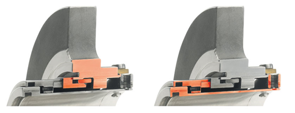
Types of Mechanical Seals for Centrifugal Pumps
- Balanced seals
- Unbalanced seals
- Pusher seals
- Non-pusher seals
- Conventional seals
- Cartridge seals
Design
A basic mechanical seal contains three sealing points.
1.The stationary part of the seal is fitted to the pump housing with a static seal –this may be sealed with an o-ring or gasket clamped between the stationary part and the pump housing.
(Highlighted in red below, left the stationary part and right the rotary portion)
2.The rotary portion of the seal is sealed onto the shaft usually with an O ring. This sealing point can also be regarded as static as this part of the seal rotates with the shaft.
3.The mechanical seal itself is the interface between the static and rotary portions of the seal.