When the crank throw is loaded by the gas pressure through the connecting rod mechanism, the arms of the crank throw deflect in the axial direction of the crankshaft, generating axial vibrations.
These vibrations may be transferred to the ship’s hull through the thrust bearing. The thrust bearing is incorporated in the aft end of the bedplate as differential expansion of the shaft and hull is minimum at the aft due to fuel heating in tanks.
The aft-most cross girder is therefore designed with ample stiffness to transmit the variable thrust from the thrust collar to the engine seating.
It is advised to align the thrust bearing when main bearing alignment is carried out to achieve accuracy.
Material
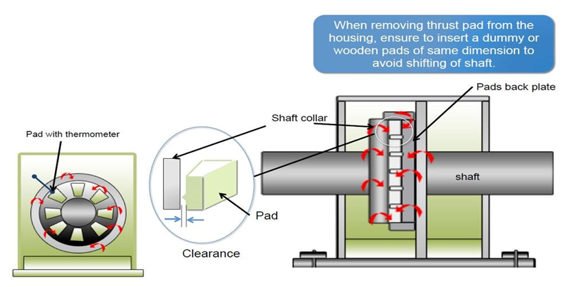
Michell type pads bearing arrangement consists of a steel forged thrust shaft, a bearing support, and segments of cast iron with white metal.
The thrust shaft is connected to the crankshaft and the intermediate shaft with fitted bolts. The thrust shaft has a collar for transfer of the ‘thrust’ through the segments to the bedplate.
Lubrication of the thrust bearing takes place from the system oil of the engine. At the bottom of the bearing there is an oil sump with an outlet to the oil pan.
Clearance
The clearance in the thrust bearing is measured during test bed trials of the engine.
For a new engine the clearance is 0.5-1.0 mm, and for an engine in service it must not exceed 2.0 mm.
Dismount the foremost segment stopper On top of the thrust segment, a wear groove of 1mm is provided (a segment with thermometer). To measure the wear, push the thrust pad with crowbar against thrust cam to eliminate any gap at the back
While Inserting feeler gauge in the groove, if 0.1 mm is not able to enter, it indicates wear is more then 0.9 mm and the bearings need to be overhauled.
If the white metal is found scored, fine scrapping can be done to wipe off the scoring marks. The liner shims can be inserted at the back of the thrust shoes to make the clearance of all thrust pads equal. This avoids uneven loading of pads