
.turbine types .impulse .types of turbine Draw copt .copt
Working principle
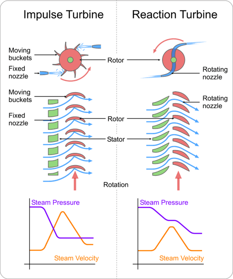
In the impulse turbine the entire pressure drop of the stage is across the fixed blades which act as nozzles. These nozzles accelerate the steam to a high velocity. This high velocity steam impinges upon the moving blades and drives them at a certain velocity. Within the moving blades the steam is turned to transfer of energy and leaves at a low velocity
In the reaction turbine the stage pressure drop is spread across both the fixed and moving blades. The fixed blades act as nozzles and accelerate the steam to a moderate velocity due to the partial pressure drop. This steam then impinges upon the moving blades and imparts some energy to them. Within the moving blades the steam is turned and accelerated by the remainder of the pressure drop.
| S/no | Impulse Turbine | Reaction Turbine |
| 1 | It consists of nozzles and moving blades | It consists of fixed blades (stators) and moving blades |
| 2 | Pressure drop occurs in nozzles and constant across moving blades | Pressure drop occurs across fixed as well as moving blades |
| 3 | Steam strikes the blades with kinetic energy | Steam strikes the blades with kinetis and pressure energy |
| 4 | It has constant blade channel area; blades are identical for various stages | It has varying blade channel area and blade sizes different for various stages |
| 5 | Due to higher pressure drop per blade, the number of stages required is less | Due to lesser pressure drop per blade, the number of stages required is more |
| 6 | Occupies less space | Occupies more space |
| 7 | Less power developed | More power developed |
| 8 | Low efficiency | High efficiency |
| 9 | Partial admission of steam possible to control output power | Partial admission of steam not possible |
| 10 | Suitable for marine applications | Suitable for industrial power generators |
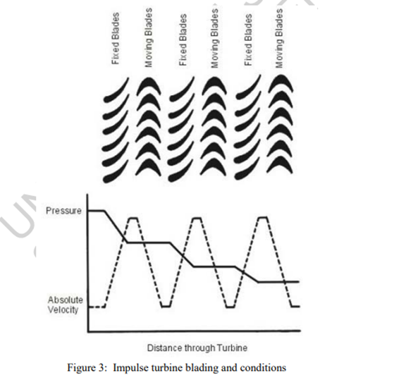
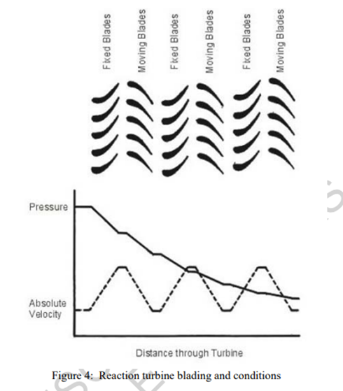
The reaction effect caused by this accelerating steam imparts more energy to the moving blades. The steam leaves the stage at a low velocity relative to the next row of fixed blades. This is illustrated in Figure 3 for impulse blading and Figure 4 for reaction blading. Figure 4: Reaction turbine blading and conditions Figure 3 shows, at the top, the end view of four stages of fixed and moving blades of an impulse turbine and, at the bottom, the pressure and velocity profiles over these four stages. Since the energy in the steam is represented by the pressure (heat energy) and velocity (kinetic energy), the conversion and transfer of energy in the blading can be visualized. Initially the pressure is high representing a high energy level. In passing through the first row of fixed blades some potential energy is converted into kinetic energy as indicated by the slight drop in pressure and increase in velocity. In passing through the mating row of moving blades the kinetic energy is transferred to the rotating wheel of the turbine as indicated by the drop in velocity. There is no change in pressure in the moving blades. It is evident that, at the exit from this first stage, the steam has given up part of its initial energy and transferred this to the rotating parts of the turbine. A similar process is repeated in the remaining three stages. Additional stages may be added to extract any remaining energy of the steam. Figure 4 shows a similar representation of four stages of fixed and moving blades of a reaction turbine given similar boundary conditions. As before, the pressure is initially high representing a high level of energy. In passing through the first row of fixed UNESCO – EOLSS SAMPLE CHAPTERS THERMAL POWER PLANTS– Vol. III – Steam Turbine Impulse and Reaction Blading – R.A. Chaplin ©Encyclopedia of Life Support Systems (EOLSS) blades some potential energy is converted into kinetic energy but not as much as in the impulse turbine. There is less of a drop in pressure and consequently a smaller increase in velocity. In passing through the mating row of moving blades there is a further drop in pressure as well as a drop in velocity. Thus the transfer of energy is in two parts, namely the transfer of kinetic energy of the steam and the transfer of some of the potential energy of the steam to the moving blades. The net result at the exit from this stage is a low velocity and a pressure somewhat lower than the initial pressure. A similar process is repeated in the remaining three stages. Any number of stages may be added to obtain the desired pressure drop across the turbine. The main difference between the impulse turbine and the reaction turbine is that, in the former, there is a pressure drop across the fixed blades only, whereas in the latter, there is a pressure drop across both the fixed and the moving blades. For similar boundary conditions this results in a lower velocity of the steam leaving the fixed blades in the case of the reaction turbine. This velocity leaving the fixed blades is relative to the fixed components and is therefore described as the absolute velocity. The velocity associated with the moving blades is known as the relative velocity (relative to the moving blades). In reaction blading the increase in velocity in the moving blades is achieved by blades designed to act as nozzles to convert some pressure energy in the steam into kinetic energy. The change in flow area in the blades governs the increase in velocity. From the continuity equation it is evident that, for small changes in density, a reduced flow area will result in an increase in velocity. The shape of the fixed blades in both impulse and reaction turbines is such as to reduce the flow area and increase the velocity. The shape of the moving blades however is not the same for impulse and reaction turbines. The moving blades of impulse turbines do not have a change in flow area. They do not therefore change the velocity of the steam but only change its direction. The moving blades of reaction turbines do have a change in flow area. They are shaped like nozzles and act to accelerate the steam as it passes through them. They also change its direction. The difference in the moving blades is evident from Figure 3 and Figure 4. In an impulse turbine the blades are symmetrical about the plane of the turbine wheel carrying the blades whereas in a reaction turbine they are not. Figure 5 and Figure 6 clarify the concept of flow areas and blade symmetry. The difference between the two is easily seen when viewing the blades from the end. In the latter figure the reduction in flow area and consequent increase in velocity is clearly evident. On an actual turbine rotor however the blades invariably have circumferential shrouding over the tips and the blade profile cannot be seen.